Blast Joint Flow Coupling
Blast Joint Flow Coupling
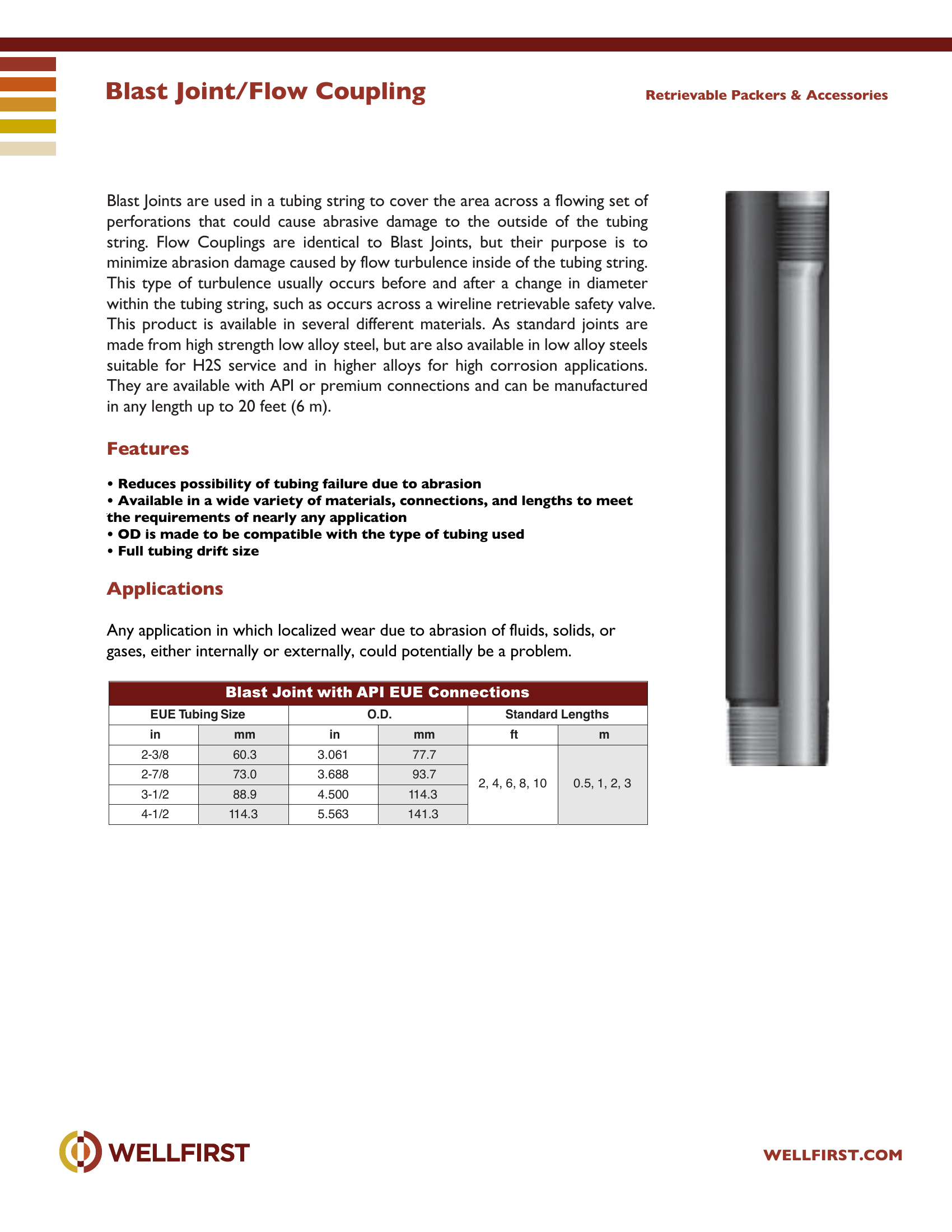
Blast Joint/Flow Coupling Blast Joints are used in a tubing string to cover the area across a flowing set of perforations that could cause abrasive damage to the outside of the tubing string. Flow Couplings are identical to Blast Joints, but their purpose is to minimize abrasion damage caused by flow turbulence inside of the tubing string. This type of turbulence usually occurs before and after a change in diameter within the tubing string, such as occurs across a wireline retrievable safety valve. This product is available in several different materials. As standard joints are made from high strength low alloy steel, but are also available in low alloy steels suitable for H2S service and in higher alloys for high corrosion applications. They are available with API or premium connections and can be manufactured in any length up to 20 feet (6 m).
Key features
- Reduces possibility of tubing failure due to abrasion
- Available in a wide variety of materials, connections, and lengths to meet the requirements of nearly any application
- OD is made to be compatible with the type of tubing used
- Full tubing drift size Applications Any application in which localized wear due to abrasion of fluids, solids, or Retrievable Packers & Accessories EUE Tubing Size O.D. Stand ard Lengths in mm in mm ft m 2-3/8 60.3 3.061 77.7 2, 4, 6, 8, 10 0.5, 1, 2, 32-7/8 73.0 3.688 93.7 3-1/2 88.9 4.500 1 14.3 4-1/2 1 14.3 5.5 63 141.3
Data sheet tables
| EUE Tubing Size in | mm | O.D. in | mm | Standard Lengths ft | m |
|---|
| 2-3/8 | 60.3 | 3.061 | 77.7 | 2, 4, 6, 8, 10 | |
| 2-7/8 | 73.0 | 3.688 | 93.7 | | |
| | | | | 0.5, 1, 2, 3 |
| 3-1/2 | 88.9 | 4.500 | 114.3 | | |
| 4-1/2 | 114.3 | 5.563 | 141.3 | | |
Complete dimensional data, part numbering and setting procedures are in the PDF.
Accessory Services|•|
Casing Scraper
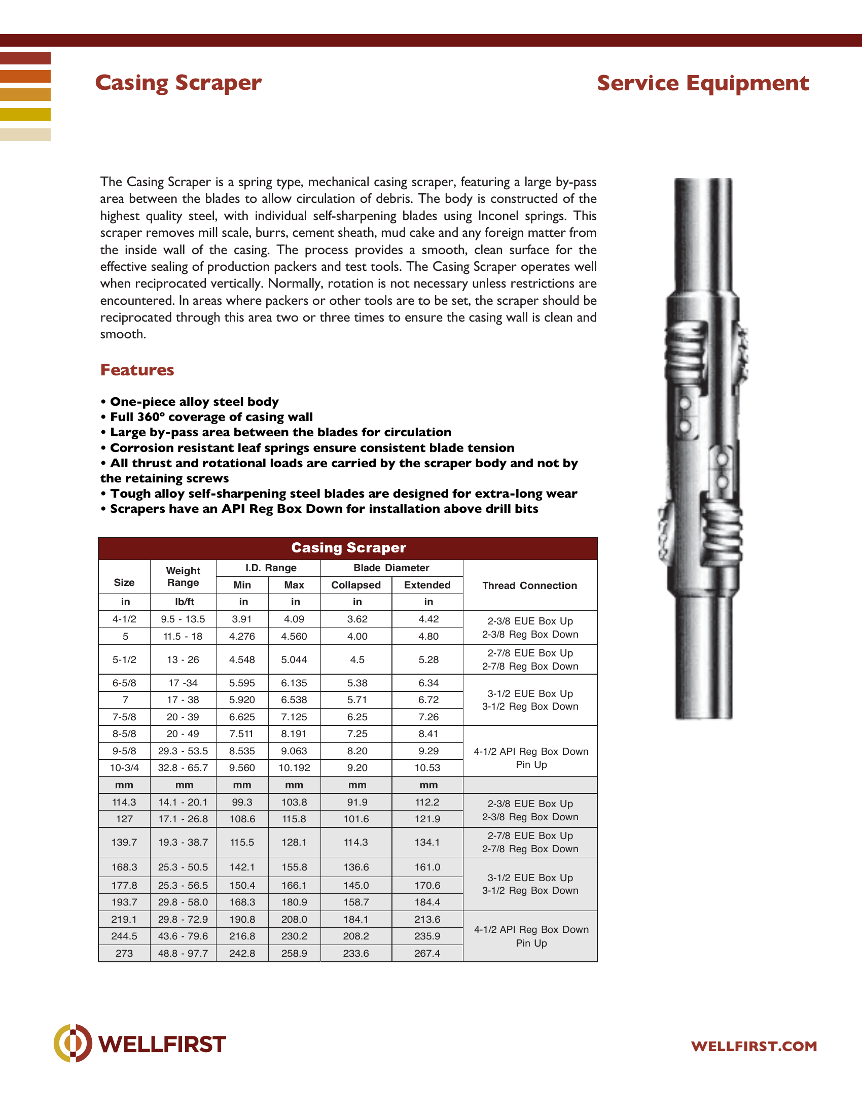
Casing Scraper The Casing Scraper is a spring type, mechanical casing scraper, featuring a large by-pass area between the blades to allow circulation of debris. The body is constructed of the highest quality steel, with individual self-sharpening blades using Inconel springs. This scraper removes mill scale, burrs, cement sheath, mud cake and any foreign matter from the inside wall of the casing. The process provides a smooth, clean surface for the effective sealing of production packers and test tools. The Casing Scraper operates well when reciprocated vertically. Normally, rotation is not necessary unless restrictions are encountered. In areas where packers or other tools are to be set, the scraper should be reciprocated through this area two or three times to ensure the casing wall is clean and smooth.
Key features
- One-piece alloy steel body
- Full 360º coverage of casing wall
- Large by-pass area between the blades for circulation
- Corrosion resistant leaf springs ensure consistent blade tension
- All thrust and rotational loads are carried by the scraper body and not by the retaining screws
- Tough alloy self-sharpening steel blades are designed for extra-long wear
Data sheet tables
| Size in | Weight Range lb/ft | I.D. Range Min in | Max in | Blade Diameter Collapsed in | Extended in | Thread Connection |
|---|
| 4-1/2 | 9.5 - 13.5 | 3.91 | 4.09 | 3.62 | 4.42 | 2-3/8 EUE Box Up 2-3/8 Reg Box Down |
| 5 | 11.5 - 18 | 4.276 | 4.560 | 4.00 | 4.80 | |
| 5-1/2 | 13 - 26 | 4.548 | 5.044 | 4.5 | 5.28 | 2-7/8 EUE Box Up 2-7/8 Reg Box Down |
| 6-5/8 | 17 -34 | 5.595 | 6.135 | 5.38 | 6.34 | 3-1/2 EUE Box Up 3-1/2 Reg Box Down |
| 7 | 17 - 38 | 5.920 | 6.538 | 5.71 | 6.72 | |
| 7-5/8 | 20 - 39 | 6.625 | 7.125 | 6.25 | 7.26 | |
| 8-5/8 | 20 - 49 | 7.511 | 8.191 | 7.25 | 8.41 | 4-1/2 API Reg Box Down Pin Up |
| 9-5/8 | 29.3 - 53.5 | 8.535 | 9.063 | 8.20 | 9.29 | |
| 10-3/4 | 32.8 - 65.7 | 9.560 | 10.192 | 9.20 | 10.53 | |
| 114.3 | 14.1 - 20.1 | 99.3 | 103.8 | 91.9 | 112.2 | 2-3/8 EUE Box Up |
| 127 | 17.1 - 26.8 | 108.6 | 115.8 | 101.6 | 121.9 | 2-3/8 Reg Box Down |
| | | | | | 2-7/8 EUE Box Up |
| 139.7 | 19.3 - 38.7 | 115.5 | 128.1 | 114.3 | 134.1 | |
| | | | | | 2-7/8 Reg Box Down |
| 168.3 | 25.3 - 50.5 | 142.1 | 155.8 | 136.6 | 161.0 | |
| | | | | | 3-1/2 EUE Box Up |
| 177.8 | 25.3 - 56.5 | 150.4 | 166.1 | 145.0 | 170.6 | |
| 193.7 | 29.8 - 58.0 | 168.3 | 180.9 | 158.7 | 184.4 | 3-1/2 Reg Box Down |
| 219.1 | 29.8 - 72.9 | 190.8 | 208.0 | 184.1 | 213.6 | |
| 244.5 | 43.6 - 79.6 | 216.8 | 230.2 | 208.2 | 235.9 | 4-1/2 API Reg Box Down |
| 273 | 48.8 - 97.7 | 242.8 | 258.9 | 233.6 | 267.4 | Pin Up |
Complete dimensional data, part numbering and setting procedures are in the PDF.
Accessory Services|•|
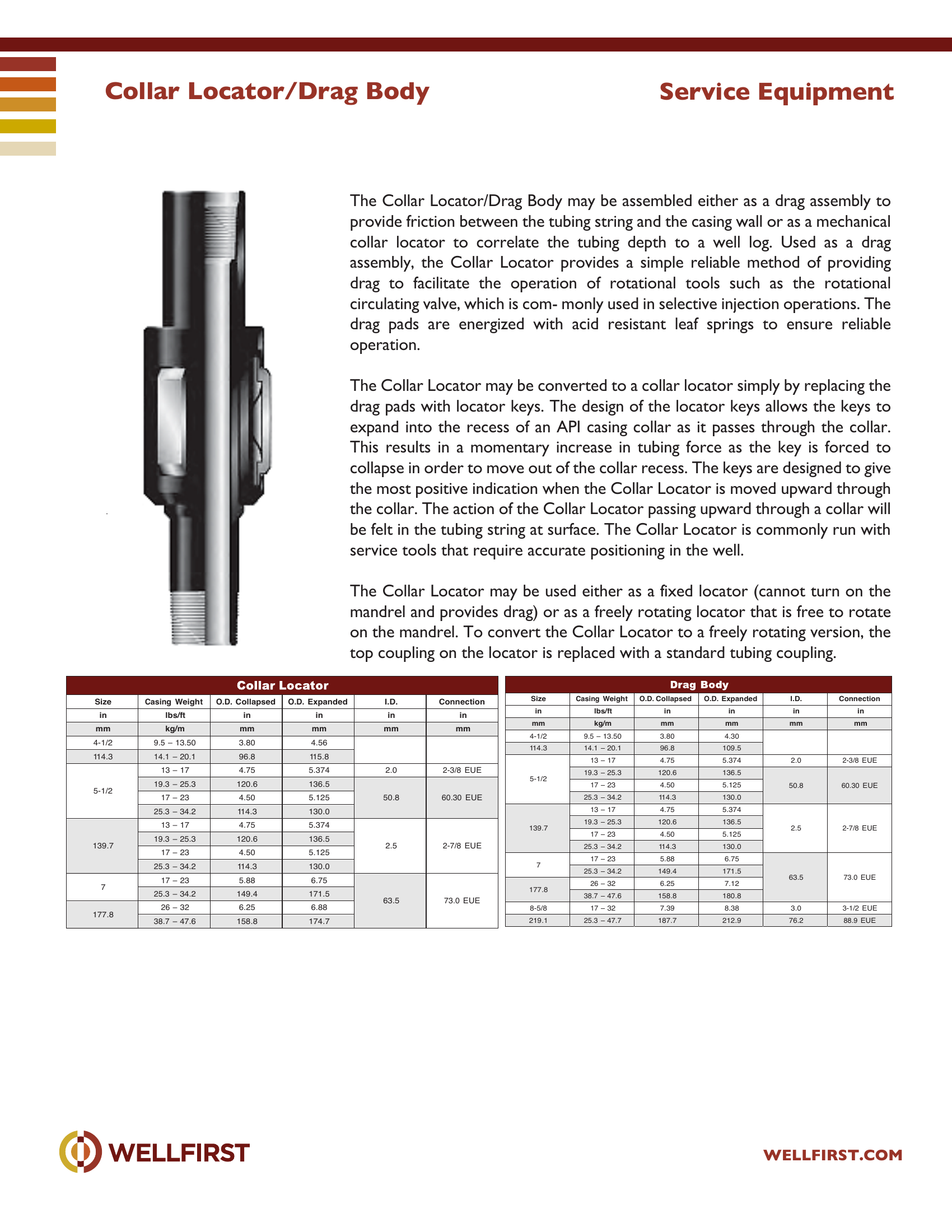
Collar Locator Drag Body
The Collar Locator/Drag Body may be assembled either as a drag assembly to provide friction between the tubing string and the casing wall or as a mechanical collar locator to correlate the tubing depth to a well log. Used as a drag assembly, the Collar Locator provides a simple reliable method of providing drag to facilitate the operation of rotational tools such as the rotational circulating valve, which is com- monly used in selective injection operations. The drag pads are energized with acid resistant leaf springs to ensure reliable operation. The Collar Locator may be converted to a collar locator simply by replacing the drag pads with locator keys. The design of the locator keys allows the keys to expand into the recess of an API casing collar as it passes through the collar. This results in a momentary increase in tubing force as the key is forced to collapse in order to move out of the collar recess. The keys are designed to give the most positive indication when the Collar Locator is moved upward through the collar. The action of the Collar Locator passing upward through a collar will be felt in the tubing string at surface. The Collar Locator is commonly run with service tools that require accurate positioning in the well. The Collar Locator may be used either as a fixed locator (cannot turn on the mandrel and provides drag) or as a freely rotating locator that is free to rotate on the mandrel. To convert the Collar Locator to a freely rotating version, the top coupling on the locator is replaced with a standard tubing coupling. Service Equipment
Data sheet tables
| Size Casing Weight | lbs/ft kg/m | in mm | in mm | in mm | in mm |
|---|
| 4-1/2 | 9.5 – 13.50 | 3.80 | 4.30 | | |
| 114.3 | 14.1 – 20.1 | 96.8 | 109.5 | | |
| 5-1/2 | 13 – 17 | 4.75 | 5.374 | 2.0 | 2-3/8 EUE |
| 19.3 – 25.3 | 120.6 | 136.5 | | |
| 17 – 23 | 4.50 | 5.125 | 50.8 | 60.30 EUE |
| 25.3 – 34.2 | 114.3 | 130.0 | | |
| 13 – 17 | 4.75 | 5.374 | 2.5 | 2-7/8 EUE |
| 19.3 – 25.3 | 120.6 | 136.5 | | |
| 139.7 | 17 – 23 | 4.50 | 5.125 | | |
| 25.3 – 34.2 | 114.3 | 130.0 | | |
| 7 | 17 – 23 | 5.88 | 6.75 | | 73.0 EUE |
| 25.3 – 34.2 26 – 32 | 149.4 6.25 | 171.5 7.12 | 63.5 | |
| 177.8 8-5/8 | 38.7 – 47.6 17 – 32 | 158.8 7.39 | 180.8 8.38 | 3.0 | 3-1/2 EUE |
| 219.1 | 25.3 – 47.7 | 187.7 | 212.9 | 76.2 | 88.9 EUE |
| Size Casing Weight | lbs/ft kg/m | in mm | in mm | in mm | in mm |
|---|
| 4-1/2 | 9.5 – 13.50 | 3.80 | 4.56 | | |
| 114.3 | 14.1 – 20.1 | 96.8 | 115.8 | | |
| 5-1/2 | 13 – 17 | 4.75 | 5.374 | 2.0 | 2-3/8 EUE |
| 19.3 – 25.3 | 120.6 | 136.5 | | |
| 17 – 23 | 4.50 | 5.125 | 50.8 | 60.30 EUE |
| 25.3 – 34.2 | 114.3 | 130.0 | | |
| 139.7 | 13 – 17 | 4.75 | 5.374 | 2.5 | 2-7/8 EUE |
| 19.3 – 25.3 | 120.6 | 136.5 | | |
| 17 – 23 | 4.50 | 5.125 | | |
| 25.3 – 34.2 17 – 23 | 114.3 5.88 | 130.0 6.75 | | |
| 7 177.8 | 25.3 – 34.2 26 – 32 | 149.4 6.25 | 171.5 6.88 | 63.5 | 73.0 EUE |
| 38.7 – 47.6 | 158.8 | 174.7 | | |
Complete dimensional data, part numbering and setting procedures are in the PDF.
Accessory Services|•|
Drift Lock Casing Scraper
Drift Lock Casing Scraper
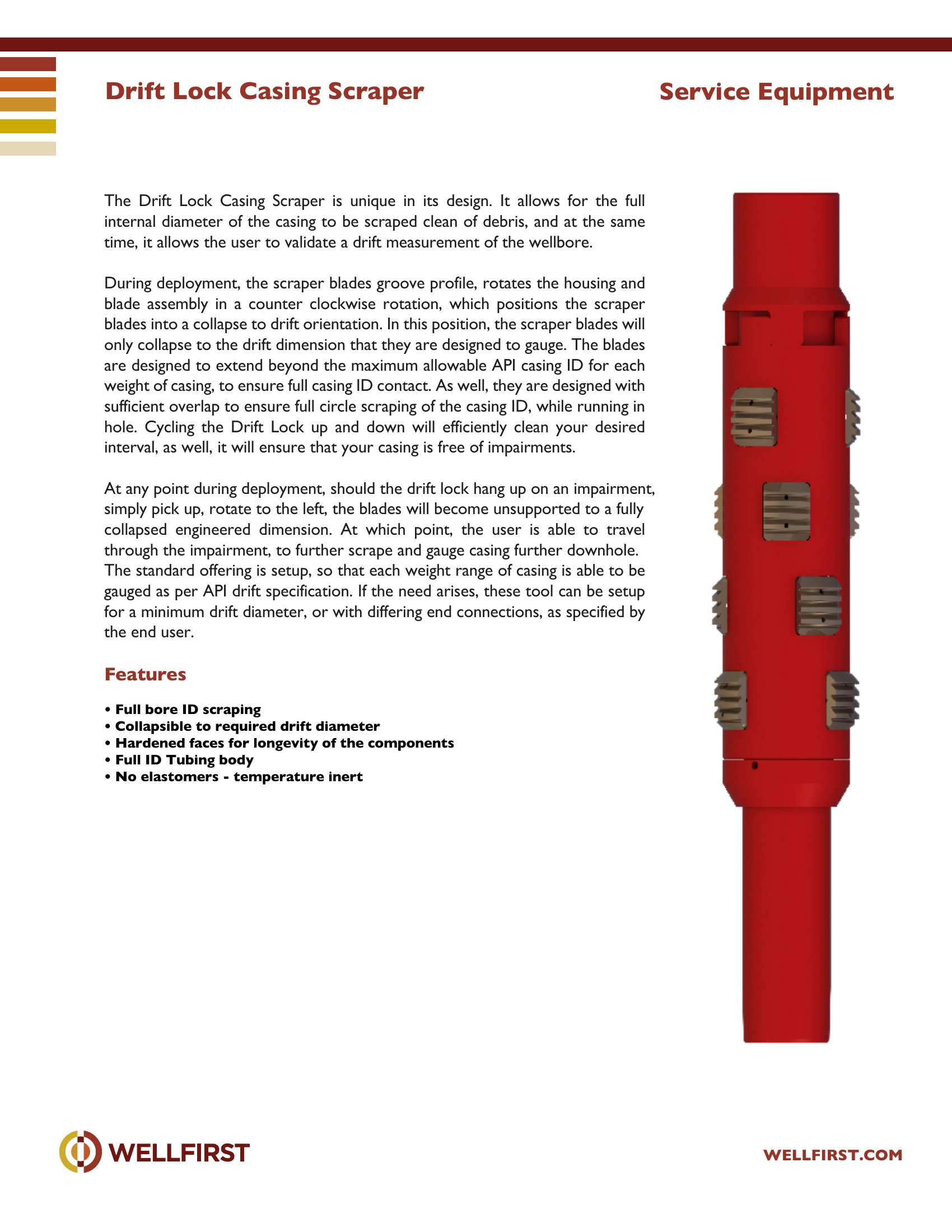
Drift Lock Casing Scraper The Drift Lock Casing Scraper is unique in its design. It allows for the full internal diameter of the casing to be scraped clean of debris, and at the same time, it allows the user to validate a drift measurement of the wellbore. During deployment, the scraper blades groove profile, rotates the housing and blade assembly in a counter clockwise rotation, which positions the scraper blades into a collapse to drift orientation. In this position, the scraper blades will only collapse to the drift dimension that they are designed to gauge. The blades are designed to extend beyond the maximum allowable API casing ID for each weight of casing, to ensure full casing ID contact. As well, they are designed with sufficient overlap to ensure full circle scraping of the casing ID, while running in hole. Cycling the Drift Lock up and down will efficiently clean your desired interval, as well, it will ensure that your casing is free of impairments. At any point during deployment, should the drift lock hang up on an impairment, simply pick up, rotate to the left, the blades will become unsupported to a fully collapsed engineered dimension. At which point, the user is able to travel through the impairment, to further scrape and gauge casing further downhole. The standard offering is setup, so that each weight range of casing is able to be gauged as per API drift specification. If the need arises, these tool can be setup for a minimum drift diameter, or with differing end connections, as specified by the end user.
Key features
- Full bore ID scraping
- Collapsible to required drift diameter
- Hardened faces for longevity of the components
- Full ID Tubing body
- No elastomers - temperature inert Service Equipment
Complete dimensional data, part numbering and setting procedures are in the PDF.
Accessory Services|•|
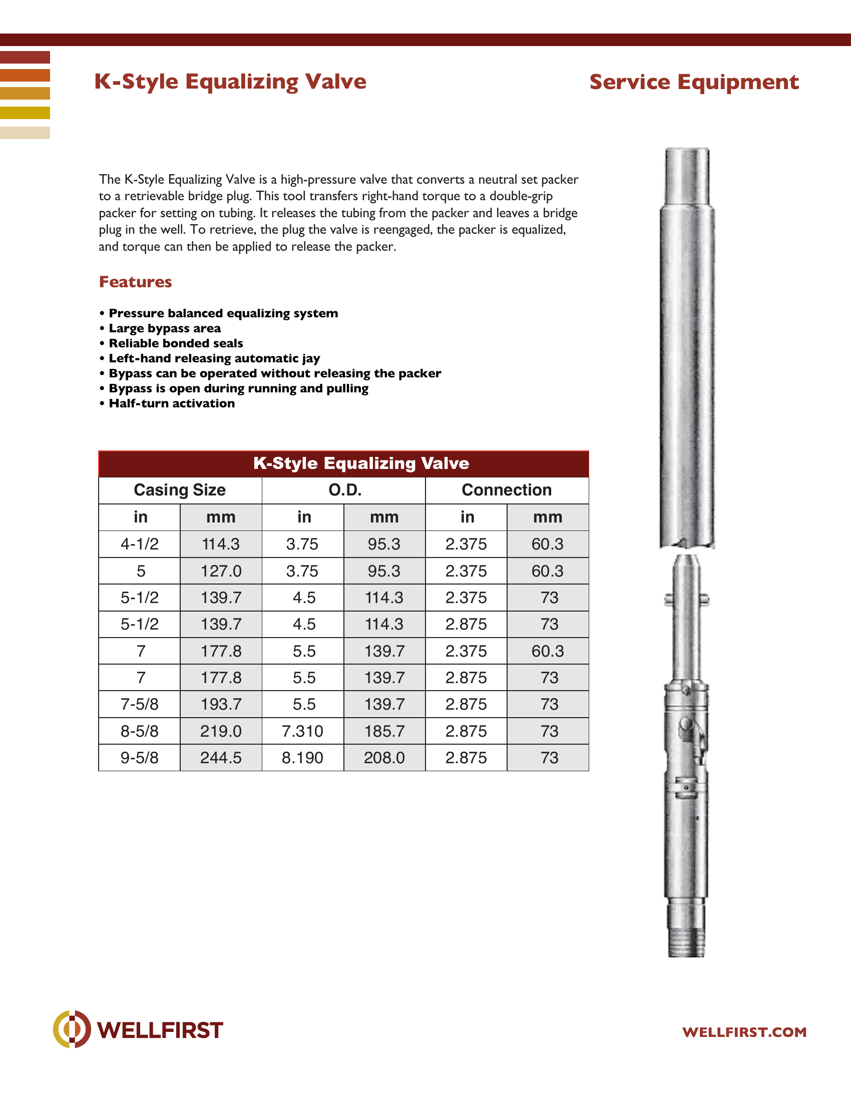
K-Style Equalizing Valve
K-Style Equalizing Valve The K-Style Equalizing Valve is a high-pressure valve that converts a neutral set packer to a retrievable bridge plug. This tool transfers right-hand torque to a double-grip packer for setting on tubing. It releases the tubing from the packer and leaves a bridge plug in the well. To retrieve, the plug the valve is reengaged, the packer is equalized, and torque can then be applied to release the packer.
Key features
- Pressure balanced equalizing system
- Large bypass area
- Reliable bonded seals
- Left-hand releasing automatic jay
- Bypass can be operated without releasing the packer
- Bypass is open during running and pulling
Data sheet tables
| Casing Size in | mm | O.D. in | mm | Connection in | mm |
|---|
| 4-1/2 | 114.3 | 3.75 | 95.3 | 2.375 | 60.3 |
| 5 | 127.0 | 3.75 | 95.3 | 2.375 | 60.3 |
| 5-1/2 | 139.7 | 4.5 | 114.3 | 2.375 | 73 |
| 5-1/2 | 139.7 | 4.5 | 114.3 | 2.875 | 73 |
| 7 | 177.8 | 5.5 | 139.7 | 2.375 | 60.3 |
| 7 | 177.8 | 5.5 | 139.7 | 2.875 | 73 |
| 7-5/8 | 193.7 | 5.5 | 139.7 | 2.875 | 73 |
| 8-5/8 | 219.0 | 7.310 | 185.7 | 2.875 | 73 |
| 9-5/8 | 244.5 | 8.190 | 208.0 | 2.875 | 73 |
Complete dimensional data, part numbering and setting procedures are in the PDF.
Accessory Services|•|
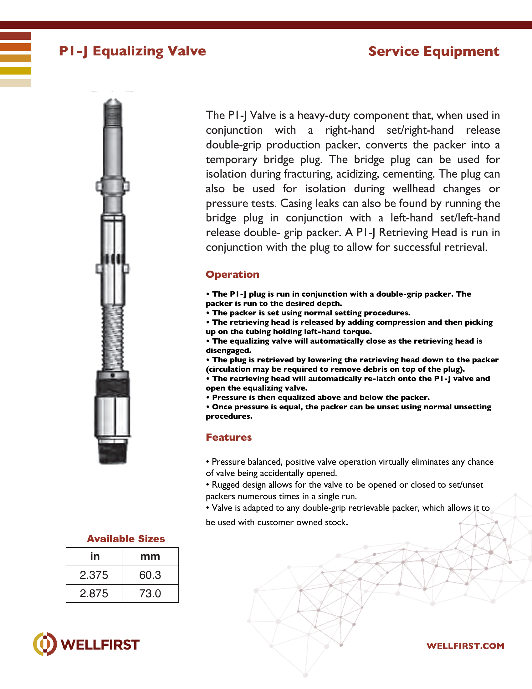
PI-J Equalizing Valve
P1-J Equalizing Valve The P1-J Valve is a heavy-duty component that, when used in conjunction with a right-hand set/right-hand release double-grip production packer, converts the packer into a temporary bridge plug. The bridge plug can be used for isolation during fracturing, acidizing, cementing. The plug can also be used for isolation during wellhead changes or pressure tests. Casing leaks can also be found by running the bridge plug in conjunction with a left-hand set/left-hand release double- grip packer. A P1-J Retrieving Head is run in conjunction with the plug to allow for successful retrieval. Operation • The P1-J plug is run in conjunction with a double-grip packer. The packer is run to the desired depth. • The packer is set using normal setting procedures. • The retrieving head is released by adding compression and then picking up on the tubing holding left-hand torque. • The equalizing valve will automatically close as the retrieving head is disengaged. • The plug is retrieved by lowering the retrieving head down to the packer (circulation may be required to remove debris on top of the plu g). • The retrieving head will automatically re-latch onto the P1-J valve and open the equalizing valve. • Pressure is then equalized above and below the packer. • Once pressure is equal, the packer can be unset using normal unsetting procedures.
Key features
- Pressure balanced, positive valve operation virtually eliminates any chance
- Rugged design allows for the valve to be opened or closed to set/unset
- Valve is adapted to any double-grip retrievable packer, which allows it to Service Equipment in mm 2.375 60.3 2.875 73.0
Data sheet tables
Complete dimensional data, part numbering and setting procedures are in the PDF.
Accessory Services|•|
SP Sand Pump
Casing Scraper The Casing Scraper is a spring type, mechanical casing scraper, featuring a large by-pass area between the blades to allow circulation of debris. The body is constructed of the highest quality steel, with individual self-sharpening blades using Inconel springs. This scraper removes mill scale, burrs, cement sheath, mud cake and any foreign matter from the inside wall of the casing. The process provides a smooth, clean surface for the effective sealing of production packers and test tools. The Casing Scraper operates well when reciprocated vertically. Normally, rotation is not necessary unless restrictions are encountered. In areas where packers or other tools are to be set, the scraper should be reciprocated through this area two or three times to ensure the casing wall is clean and smooth.
Key features
- One-piece alloy steel body
- Full 360º coverage of casing wall
- Large by-pass area between the blades for circulation
- Corrosion resistant leaf springs ensure consistent blade tension
- All thrust and rotational loads are carried by the scraper body and not by the retaining screws
- Tough alloy self-sharpening steel blades are designed for extra-long wear
Data sheet tables
| Size in | Weight Range lb/ft | I.D. Range Min in | Max in | Blade Diameter Collapsed in | Extended in | Thread Connection |
|---|
| 4-1/2 | 9.5 - 13.5 | 3.91 | 4.09 | 3.62 | 4.42 | 2-3/8 EUE Box Up 2-3/8 Reg Box Down |
| 5 | 11.5 - 18 | 4.276 | 4.560 | 4.00 | 4.80 | |
| 5-1/2 | 13 - 26 | 4.548 | 5.044 | 4.5 | 5.28 | 2-7/8 EUE Box Up 2-7/8 Reg Box Down |
| 6-5/8 | 17 -34 | 5.595 | 6.135 | 5.38 | 6.34 | 3-1/2 EUE Box Up 3-1/2 Reg Box Down |
| 7 | 17 - 38 | 5.920 | 6.538 | 5.71 | 6.72 | |
| 7-5/8 | 20 - 39 | 6.625 | 7.125 | 6.25 | 7.26 | |
| 8-5/8 | 20 - 49 | 7.511 | 8.191 | 7.25 | 8.41 | 4-1/2 API Reg Box Down Pin Up |
| 9-5/8 | 29.3 - 53.5 | 8.535 | 9.063 | 8.20 | 9.29 | |
| 10-3/4 | 32.8 - 65.7 | 9.560 | 10.192 | 9.20 | 10.53 | |
| 114.3 | 14.1 - 20.1 | 99.3 | 103.8 | 91.9 | 112.2 | 2-3/8 EUE Box Up |
| 127 | 17.1 - 26.8 | 108.6 | 115.8 | 101.6 | 121.9 | 2-3/8 Reg Box Down |
| | | | | | 2-7/8 EUE Box Up |
| 139.7 | 19.3 - 38.7 | 115.5 | 128.1 | 114.3 | 134.1 | |
| | | | | | 2-7/8 Reg Box Down |
| 168.3 | 25.3 - 50.5 | 142.1 | 155.8 | 136.6 | 161.0 | |
| | | | | | 3-1/2 EUE Box Up |
| 177.8 | 25.3 - 56.5 | 150.4 | 166.1 | 145.0 | 170.6 | |
| 193.7 | 29.8 - 58.0 | 168.3 | 180.9 | 158.7 | 184.4 | 3-1/2 Reg Box Down |
| 219.1 | 29.8 - 72.9 | 190.8 | 208.0 | 184.1 | 213.6 | |
| 244.5 | 43.6 - 79.6 | 216.8 | 230.2 | 208.2 | 235.9 | 4-1/2 API Reg Box Down |
| 273 | 48.8 - 97.7 | 242.8 | 258.9 | 233.6 | 267.4 | Pin Up |
Complete dimensional data, part numbering and setting procedures are in the PDF.
Accessory Services|•|
Splined Expansion Joint
10,000 psi
Splined Expansion Joint
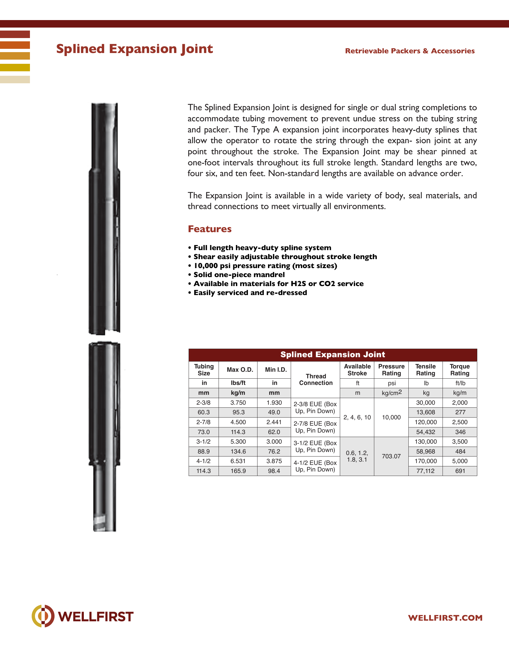
Splined Expansion Joint The Splined Expansion Joint is designed for single or dual string completions to accommodate tubing movement to prevent undue stress on the tubing string and packer. The Type A expansion joint incorporates heavy-duty splines that allow the operator to rotate the string through the expan- sion joint at any point throughout the stroke. The Expansion Joint may be shear pinned at one-foot intervals throughout its full stroke length. Standard lengths are two, four six, and ten feet. Non-standard lengths are available on advance order. The Expansion Joint is available in a wide variety of body, seal materials, and
Key features
- Full length heavy-duty spline system
- Shear easily adjustable throughout stroke length
- 10,000 psi pressure rating (most sizes)
- Solid one-piece mandrel
- Available in materials for H2S or CO2 service
- Easily serviced and re-dressed Retrievable Packers & Accessories Size Max O.D. Min I. D. in lbs/ft in ft psi lb ft/lb mm kg/m mm m kg/cm2 kg kg/m 2-3/8 3.750 1.930 2-3/8 EUE (Box Up, Pi n Down) 2, 4, 6, 10 10,00 0 30,00 0 2,000 60.3 95.3 49.0 13,608 277 2-7/8 4.500 2.441 2-7/8 EUE (Box Up, Pi n Down) 120,000 2,500 73.0 114.3 62.0 54,432 346 3-1/2 5.300 3.000 3-1/2 EUE (Box Up, Pi n Down) 0.6, 1.2, 1.8, 3.1 703.07 130,0 00 3,500 88.9 134.6 76.2 58,968 484 4-1/2 6.531 3.875 4-1/2 EUE (Box Up, Pi n Down) 170,000 5,000 114.3 165.9 98.4 77,112 691
| Data sheet rating | Value |
|---|
| Max pressure (data sheet) | 10,000 psi |
Data sheet tables
| Tubing Size in mm | Max O.D. lbs/ft kg/m | Min I.D. in mm | Thread Connection | Available Stroke ft m | Pressure Rating psi kg/cm2 | Tensile Rating lb kg | Torque Rating ft/lb kg/m |
|---|
| 2-3/8 | 3.750 | 1.930 | 2-3/8 EUE (Box Up, Pin Down) | 2, 4, 6, 10 | 10,000 | 30,000 | 2,000 |
| 60.3 | 95.3 | 49.0 | | | | 13,608 | 277 |
| 2-7/8 | 4.500 | 2.441 | 2-7/8 EUE (Box Up, Pin Down) | | | 120,000 | 2,500 |
| 73.0 | 114.3 | 62.0 | | | | 54,432 | 346 |
| 3-1/2 | 5.300 | 3.000 | 3-1/2 EUE (Box Up, Pin Down) | | | 130,000 | 3,500 |
| 88.9 | 134.6 | 76.2 | | | | 58,968 | 484 |
| | | | 0.6, 1.2, | | | |
| | | | | 703.07 | | |
| 4-1/2 | 6.531 | 3.875 | 4-1/2 EUE (Box Up, Pin Down) | 1.8, 3.1 | | 170,000 | 5,000 |
| 114.3 | 165.9 | 98.4 | | | | 77,112 | 691 |
Complete dimensional data, part numbering and setting procedures are in the PDF.
Accessory Services|•|
Three Turn Rotational Circulating Valve
5,000 psi
Three Turn Rotational Circulating Valve
Three Turn Rotational Circulating Valve The Three-Turn Rotational Circulating Valve is a rotational pressure balanced valve that is opened or closed by three turns to the right or left respectively. This valve can be run with SST tools, straddle packers, inflatables, packers, etc. allowing communication between tubing and annulus.
Key features
- Rated to 5,000 psi differential pressure
- Large ports allow fluids to pass through easily when circulating Operation
- Three turns to the left to close
- Three turns to the right to open Service Equipment Size O.D. I.D . Thread Connection in mm in mm in mm in mm 4-1/2 114.3 3.75 95.2 1.90 48.2 2-3/8 EUE 60.3 7 177.8 5.0 127.0 2.25 57.1 2-7/8 EUE 73.0
| Data sheet rating | Value |
|---|
| Max pressure (data sheet) | 5,000 psi |
Data sheet tables
| Size in | mm | O.D. in | mm | I.D. in | mm | Thread Connection in | mm |
|---|
| 4-1/2 | | 3.75 | 95.2 | 1.90 | | 2-3/8 EUE | |
| 114.3 | | | | 48.2 | | 60.3 |
| 7 | | 5.0 | 127.0 | 2.25 | | 2-7/8 EUE | |
| 177.8 | | | | 57.1 | | 73.0 |
Complete dimensional data, part numbering and setting procedures are in the PDF.
Accessory Services|•|