
Wellfirst

WELLFIRST | a greater focus

PRODUCTS & SERVICES

Completion Packers

Wellfirst completion packers span retrievable and permanent designs that isolate, hang off and protect downhole investments across the life of the well. Element packages can be configured for the fluids, temperatures and differential pressures your completion string will see.

Applications

Production and injection isolation, gas-lift compatibility, zonal testing and casing corrosion protection.

Configurable

Element compounds, sizes and connection selections can be matched to your completion design.

Technical depth

Each tool has its own print-ready spec sheet derived from the data PDF.

Completion Packers — 13 products

AD-I Tension Packer

AD-I Tension Packer

PDF
AD-I Tension Packer

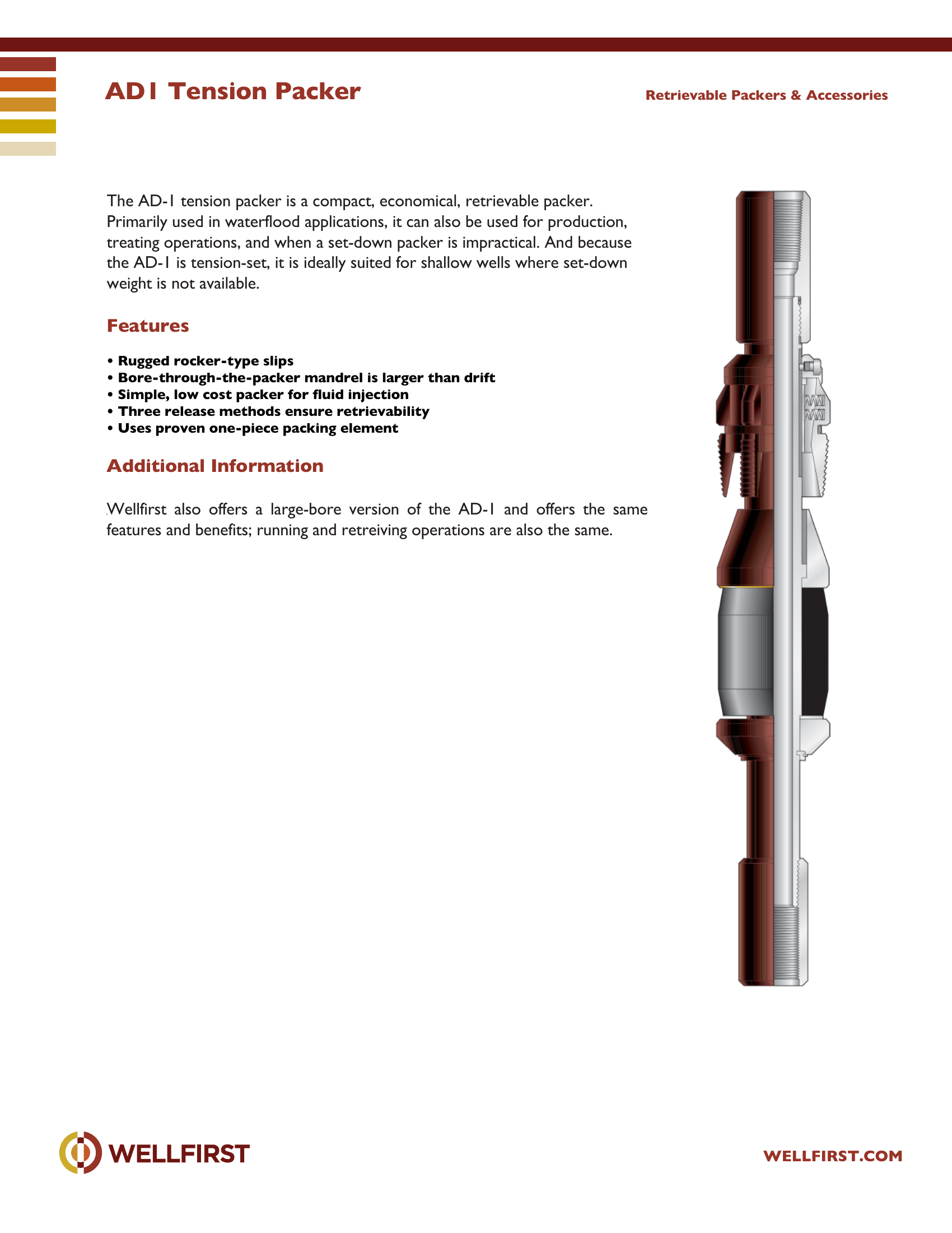
AD1 Tension Packer The AD-1 tension packer is a compact, economical, retrievable packer. Primarily used in waterflood applications, it can also be used for production, treating operations, and when a set-down packer is impractical. And because the AD-1 is tension-set, it is ideally suited for shallow wells where set-down weight is not available.

Key features
  • Rugged rocker-type slips
  • Bore-through-the-packer mandrel is larger than drift
  • Simple, low cost packer for fluid injection
  • Three release methods ensure retrievability
  • Uses proven one-piece packing element Additional Information Wellfirst also offers a large-bore version of the AD-1 and offers the same Retrievable Packers & Accessories

Complete dimensional data, part numbering and setting procedures are in the PDF.
Completion Packers|•| 
Full data sheet (PDF)
AR-10 Double Grip Mechanical Packer

AR-10 Double Grip Mechanical Packer

10,000 psi
PDF
AR-10 Double Grip Mechanical Packer

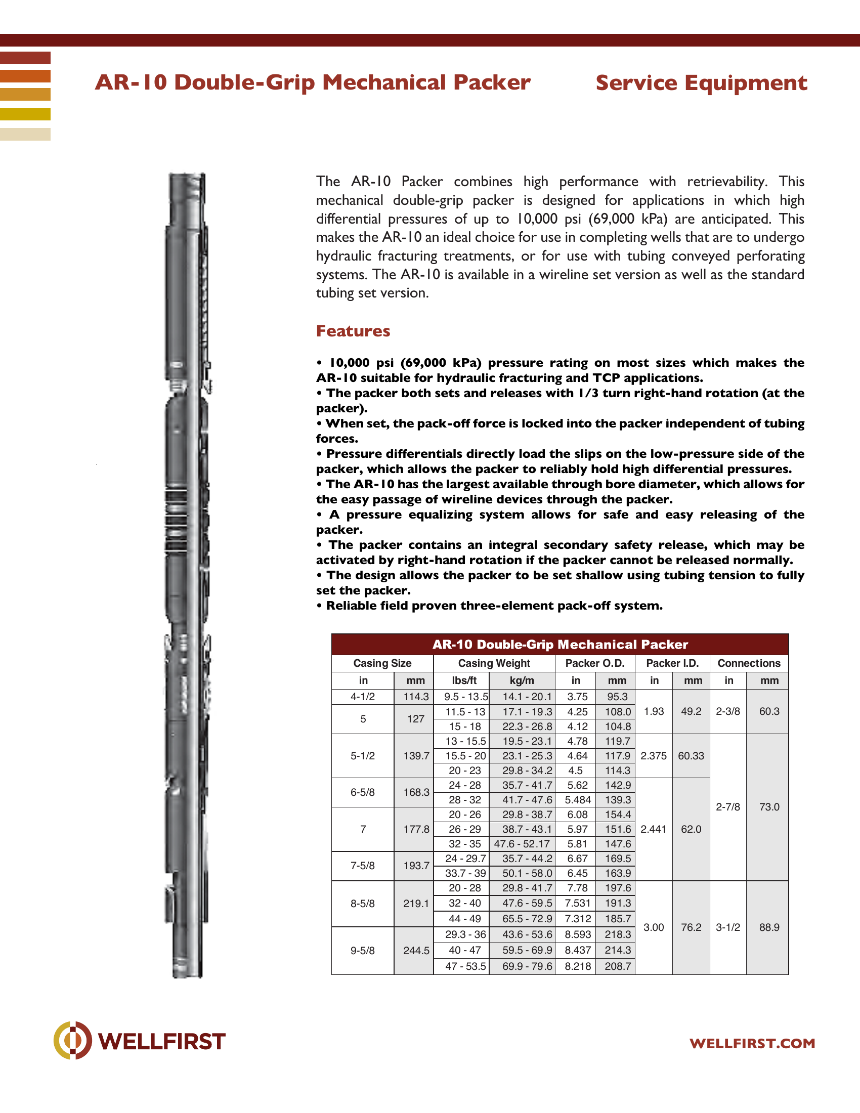
AR-10 Double-Grip Mechanical Packer The AR-10 Packer combines high performance with retrievability. This mechanical double-grip packer is designed for applications in which high differential pressures of up to 10,000 psi (69,000 kPa) are anticipated. This makes the AR-10 an ideal choice for use in completing wells that are to undergo hydraulic fracturing treatments, or for use with tubing conveyed perforating systems. The AR-10 is available in a wireline set version as well as the standard tubing set version.

Key features
  • 10,000 psi (69,000 kPa) pressure rating on most sizes which makes the AR-10 suitable for hydraulic fracturing and TCP applications.
  • The packer both sets and releases with 1/3 turn right-hand rotation (at the
  • When set, the pack-off force is locked into the packer independent of tubing
  • Pressure differentials directly load the slips on the low-pressure side of the
  • The AR-10 has the largest available through bore diameter, which allows for
  • A pressure equalizing system allows for safe and easy releasing of the
Data sheet ratingValue
Max pressure (data sheet)10,000 psi
Data sheet tables
Casing Size Casingmmlbs/ftkg/minmminmminmm
4-1/2114.39.5 - 13 .514.1 - 20 .13.7595.31.932-3/8
511.5 - 1317.1 - 19 .34.25108.049.260.3
127
15 - 1822.3 - 26 .84.12104.8
5-1/213 - 15.519.5 - 23 .14.78119.72.3752-7/8
139.715.5 - 2023.1 - 25 .34.64117.960.33
20 - 2329.8 - 34 .24.5114.3
6-5/824 - 2835.7 - 41 .75.62142.92.441
168.3
28 - 3241.7 - 47 .65.484139.3
73.0
720 - 2629.8 - 38 .76.08154.4
177.826 - 2938.7 - 43 .15.97151.662.0
32 - 3547.6 - 52 .175.81147.6
7-5/824 - 29.735.7 - 44 .26.67169.5
193.7
33.7 - 3950.1 - 58 .06.45163.9
8-5/820 - 2829.8 - 41 .77.78197.63.003-1/2
219.132 - 4047.6 - 59 .57.531191.3
44 - 4965.5 - 72 .97.312185.7
76.288.9
9-5/829.3 - 3643.6 - 53 .68.593218.3
244.540 - 4759.5 - 69 .98.437214.3
47 - 53.569.9 - 79 .68.218208.7

Complete dimensional data, part numbering and setting procedures are in the PDF.

Completion Packers|•| 
Full data sheet (PDF)
AS-1 Retrievable Packer

AS-1 Retrievable Packer

PDF
AS-1 Retrievable Packer

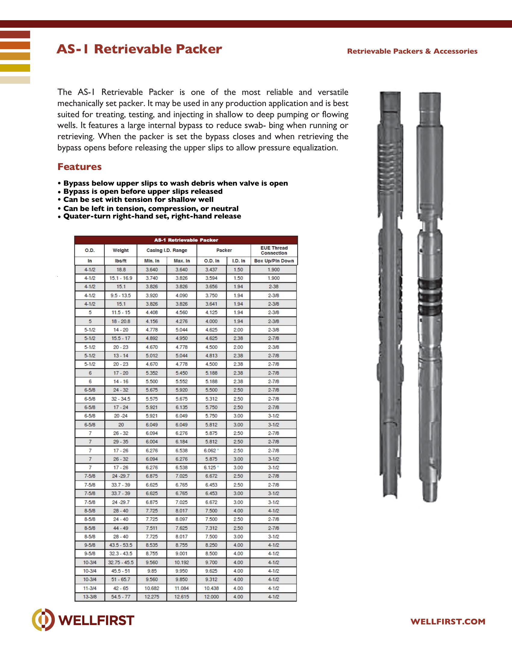
AS-1 Retrievable Packer The AS-1 Retrievable Packer is one of the most reliable and versatile mechanically set packer. It may be used in any production application and is best suited for treating, testing, and injecting in shallow to deep pumping or flowing wells. It features a large internal bypass to reduce swab- bing when running or retrieving. When the packer is set the bypass closes and when retrieving the bypass opens before releasing the upper slips to allow pressure equalization.

Key features
  • Bypass below upper slips to wash debris when valve is open
  • Bypass is open before upper slips released
  • Can be set with tension for shallow well
  • Can be left in tension, compression, or neutral
  • Quater-turn right-hand set, right-hand release Retrievable Packers & Accessories

Complete dimensional data, part numbering and setting procedures are in the PDF.
Completion Packers|•| 
Full data sheet (PDF)
Coiled Tubing Packer Isolation Tool

Coiled Tubing Packer Isolation Tool

PDF
Coiled Tubing Packer Isolation Tool

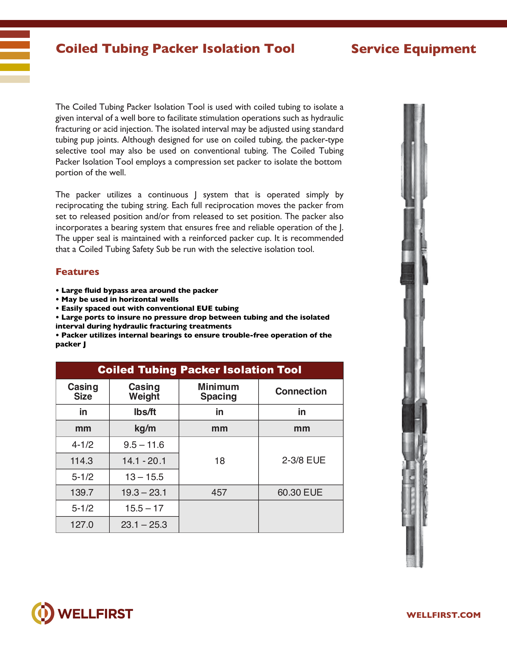
Coiled Tubing Packer Isolation Tool The Coiled Tubing Packer Isolation Tool is used with coiled tubing to isolate a given interval of a well bore to facilitate stimulation operations such as hydraulic fracturing or acid injection. The isolated interval may be adjusted using standard tubing pup joints. Although designed for use on coiled tubing, the packer-type selective tool may also be used on conventional tubing. The Coiled Tubing Packer Isolation Tool employs a compression set packer to isolate the bottom portion of the well. The packer utilizes a continuous J system that is operated simply by reciprocating the tubing string. Each full reciprocation moves the packer from set to released position and/or from released to set position. The packer also incorporates a bearing system that ensures free and reliable operation of the J. The upper seal is maintained with a reinforced packer cup. It is recommended that a Coiled Tubing Safety Sub be run with the selective isolation tool.

Key features
  • Large fluid bypass area around the packer
  • May be used in horizontal wells
  • Easily spaced out with conventional EUE tubing
  • Large ports to insure no pressure drop between tubing and the isolated interval during hydraulic fracturing treatments
  • Packer utilizes internal bearings to ensure trouble-free operation of the packer J Service Equipment Casing Size Casing Weight Minimum Sp acing Connect ion in lbs/ft in in mm kg/m mm mm 4-1/2 9.5 – 11.6 18 2-3/8 EUE114.3 14.1 - 20 .1 5-1/2 13 – 15 .5 139.7 19.3 – 23.1 457 60.30 EUE 5-1/2 15.5 – 17 127.0 23.1 – 25.3
Data sheet tables
Casing Size in mmCasing Weight lbs/ft kg/mMinimum Spacing in mmConnect ion in mm
4-1/29.5 – 11.6182-3/8 EUE
114.314.1 - 20 .1
5-1/213 – 15.5
139.719.3 – 23.145760.30 EUE
5-1/215.5 – 17
127.023.1 – 25.3

Complete dimensional data, part numbering and setting procedures are in the PDF.
Completion Packers|•| 
Full data sheet (PDF)
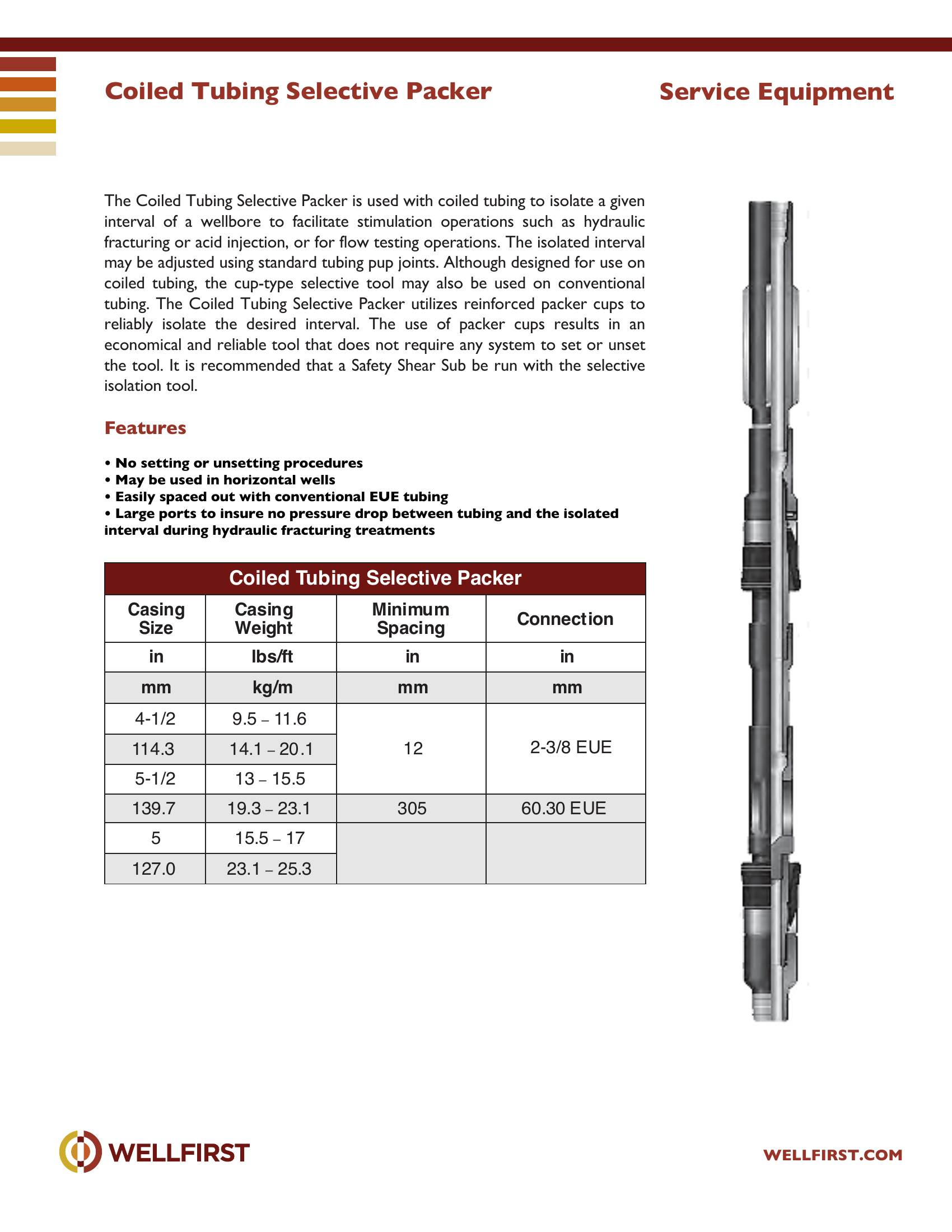
Coiled Tubing Selective Packer

Coiled Tubing Selective Packer

PDF
Coiled Tubing Selective Packer
Key features
  • No setting or unsetting procedures
  • May be used in horizontal wells
  • Easily spaced out with conventional EUE tubing
  • Large ports to insure no pressure drop between tubing and the isolated interval during hydraulic fracturing treatments Service Equipment Coiled Tubing Selective Packer Casing Size Casing Weight Minimum Sp acing Connect ion in lbs/ft in in mm kg/m mm mm 4-1/2 9.5 – 11.6 12 2-3/8 EUE114.3 14.1 – 20 .1 5-1/2 13 – 15.5 139.7 19.3 – 23.1 305 60.30 EUE 5 15.5 – 17 127.0 23.1 – 25.3
Data sheet tables
Coiled Tubing SelectiveCasing Weight lbs/ftMinimum Spacing inConnect ion in
4-1/29.5 – 11.6122-3/8 EUE
114.314.1 – 20 .1
5-1/213 – 15.5
139.719.3 – 23.130560.30 EUE
515.5 – 17
127.023.1 – 25.3

Complete dimensional data, part numbering and setting procedures are in the PDF.
Completion Packers|•| 
Full data sheet (PDF)
Coiled Tubing Tension Packer

Coiled Tubing Tension Packer

PDF
Coiled Tubing Tension Packer

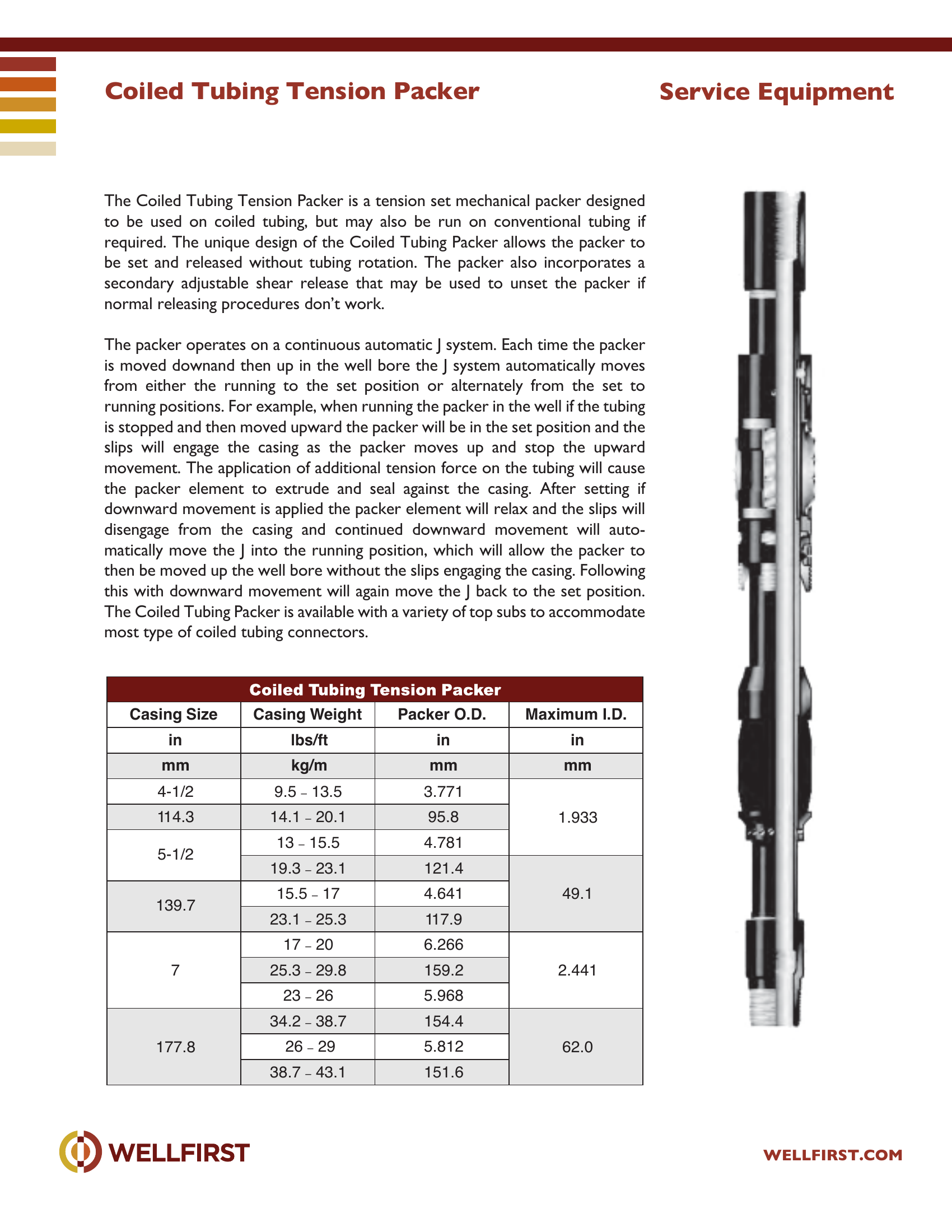
The Coiled Tubing Tension Packer is a tension set mechanical packer designed to be used on coiled tubing, but may also be run on conventional tubing if required. The unique design of the Coiled Tubing Packer allows the packer to be set and released without tubing rotation. The packer also incorporates a secondary adjustable shear release that may be used to unset the packer if normal releasing procedures don’t work. The packer operates on a continuous automatic J system. Each time the packer is moved downand then up in the well bore the J system automatically moves from either the running to the set position or alternately from the set to running positions. For example, when running the packer in the well if the tubing is stopped and then moved upward the packer will be in the set position and the slips will engage the casing as the packer moves up and stop the upward movement. The application of additional tension force on the tubing will cause the packer element to extrude and seal against the casing. After setting if downward movement is applied the packer element will relax and the slips will disengage from the casing and continued downward movement will auto- matically move the J into the running position, which will allow the packer to then be moved up the well bore without the slips engaging the casing. Following this with downward movement will again move the J back to the set position. The Coiled Tubing Packer is available with a variety of top subs to accommodate most type of coiled tubing connectors. Service Equipment Casing Size Casing Weight Packer O.D. Maximum I.D. in lbs/ft in in mm kg/m mm mm 4-1/2 9.5 –

Data sheet tables
Casing Size in mmCasing Weight lbs/ft kg/mPacker O.D. in mmMaximum I.D. in mm
4-1/29.5 – 13.53.7711.933
114.314.1 – 20.195.8
5-1/213 – 15.54.781
19.3 – 23.1121.4
15.5 – 174.64149.1
139.7
23.1 – 25.3117.9
717 – 206.2662.441
25.3 – 29.8159.2
23 – 265.968
34.2 – 38.7154.4
177.826 – 295.81262.0
38.7 – 43.1151.6

Complete dimensional data, part numbering and setting procedures are in the PDF.
Completion Packers|•| 
Full data sheet (PDF)
HydroSeal Dual Retrievable Packer

HydroSeal Dual Retrievable Packer

PDF
HydroSeal Dual Retrievable Packer

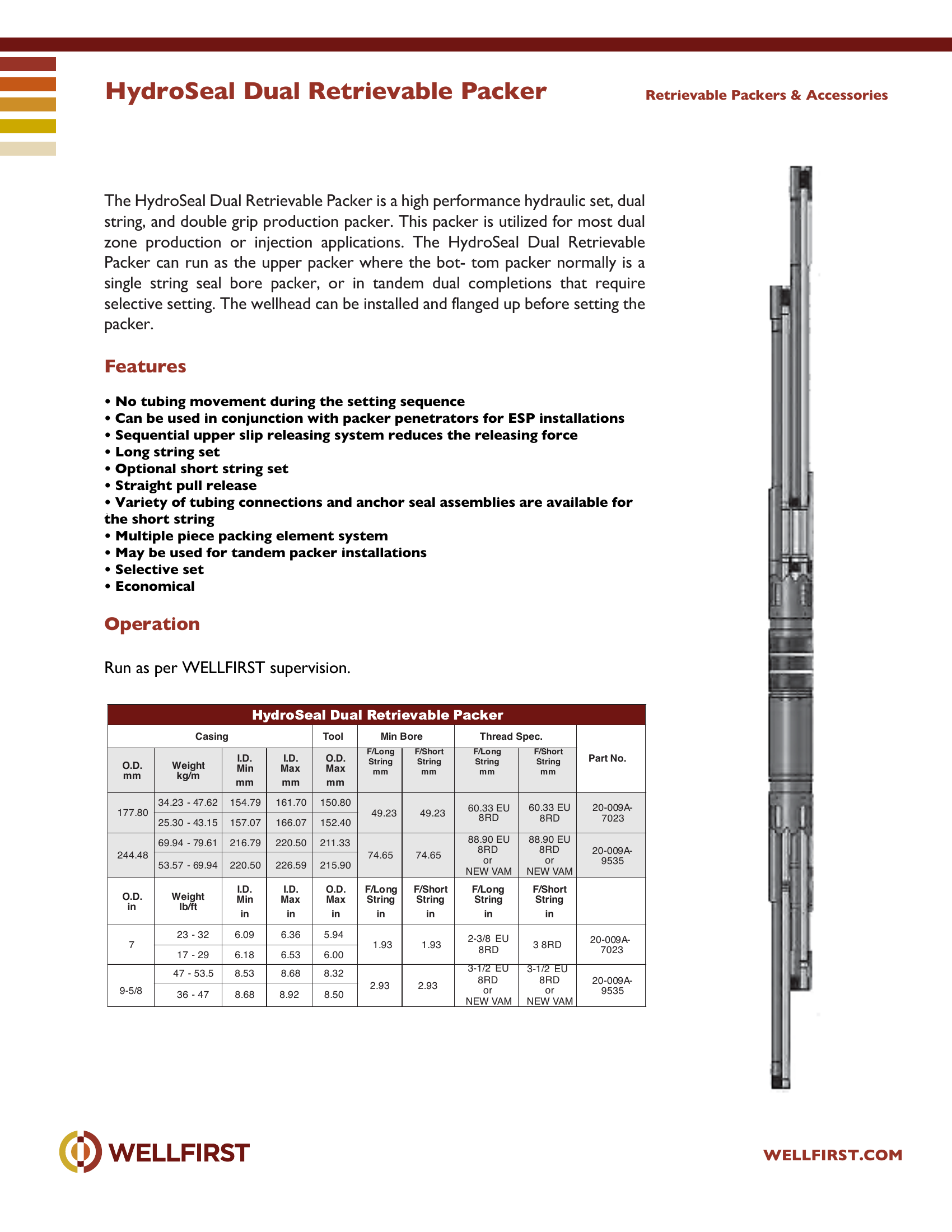
HydroSeal Dual Retrievable Packer The HydroSeal Dual Retrievable Packer is a high performance hydraulic set, dual string, and double grip production packer. This packer is utilized for most dual zone production or injection applications. The HydroSeal Dual Retrievable Packer can run as the upper packer where the bot- tom packer normally is a single string seal bore packer, or in tandem dual completions that require selective setting. The wellhead can be installed and flanged up before setting the packer.

Key features
  • No tubing movement during the setting sequence
  • Can be used in conjunction with packer penetrators for ESP installations
  • Sequential upper slip releasing system reduces the releasing force
  • Long string set
  • Optional short string set
  • Straight pull release
Data sheet tables
Casing O.D. mmWeight kg/mI.D. Min mmI.D. Max mmTool O.D. Max mmMin Bore F/Long String mmF/Short String mmThread Spec. F/Long String mmF/Short String mmPart No.
177.8034.23 - 47.62154.79161.70150.8049.2349.2360.33 EU 8RD60.33 EU 8RD20-009A- 7023
25.30 - 43.15157.07166.07152.40
244.4869.94 - 79.61216.79220.50211.3374.6588.90 EU 8RD or NEW VAM88.90 EU 8RD or NEW VAM20-009A- 9535
53.57 - 69.94220.50226.59215.9074.65
O.D. inWeight lb/ftI.D. Min inI.D. Max inO.D. Max inF/Long String inF/Short String inF/Long String inF/Short String in
723 - 326.096.365.941.931.932-3/8EU 8RD3 8RD20-009A- 7023
17 - 296.186.536.00
9-5/847 - 53.58.538.688.322.932.933-1/2 EU 8RD or NEW VAM3-1/2 EU 8RD or NEW VAM20-009A- 9535
36 - 478.688.928.50

Complete dimensional data, part numbering and setting procedures are in the PDF.
Completion Packers|•| 
Full data sheet (PDF)
Limit 75 Double-Group Mechanical Packer

Limit 75 Double-Group Mechanical Packer

7,500 psi
PDF
Limit 75 Double-Group Mechanical Packer

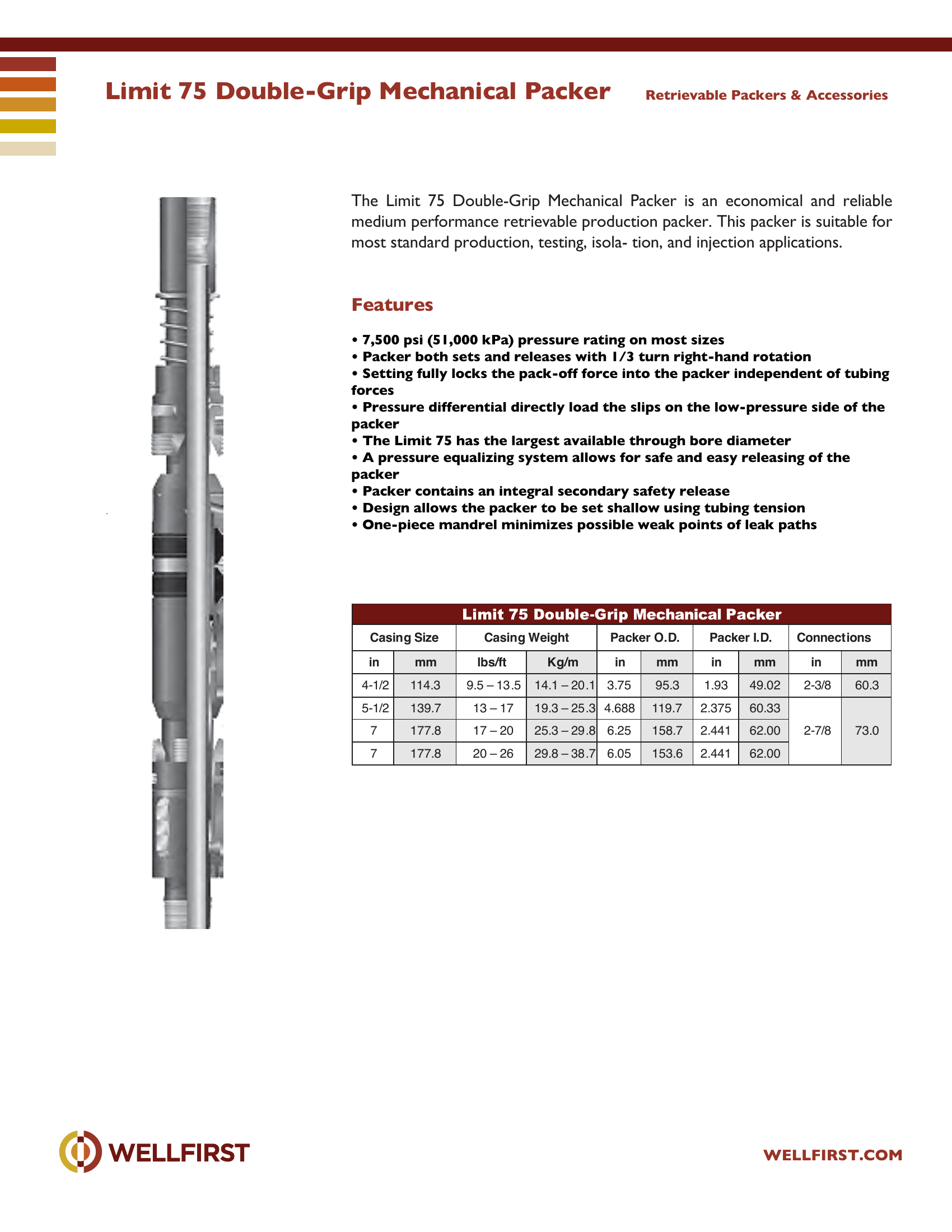
Limit 75 Double-Grip Mechanical Packer The Limit 75 Double-Grip Mechanical Packer is an economical and reliable medium performance retrievable production packer. This packer is suitable for most standard production, testing, isola- tion, and injection applications.

Key features
  • 7,500 psi (51,000 kPa) pressure rating on most sizes
  • Packer both sets and releases with 1/3 turn right-hand rotati on
  • Setting fully locks the pack-off force into the packer independent of tubing forces
  • Pressure differential directly load the slips on the low-pressure side of the packer
  • The Limit 75 has the largest available through bore diameter
  • A pressure equalizing system allows for safe and easy releasing of the packer
Data sheet ratingValue
Max pressure (data sheet)7,500 psi
Data sheet tables
Casing Size Casingmmlbs/ftKg/minmminmminmm
4-1/2114.39.5 – 13 .514.1 – 20 .13.7595.31.9349.022-3/860.3
5-1/2139.713 – 1719.3 – 25 .34.688119.72.37560.332-7/8
7177.817 – 2025.3 – 29 .86.25158.72.44162.0073.0
7177.820 – 2629.8 – 38 .76.05153.62.44162.00

Complete dimensional data, part numbering and setting procedures are in the PDF.
Completion Packers|•| 
Full data sheet (PDF)
SR-3 Double Grip Retrievable Packer

SR-3 Double Grip Retrievable Packer

PDF
SR-3 Double Grip Retrievable Packer

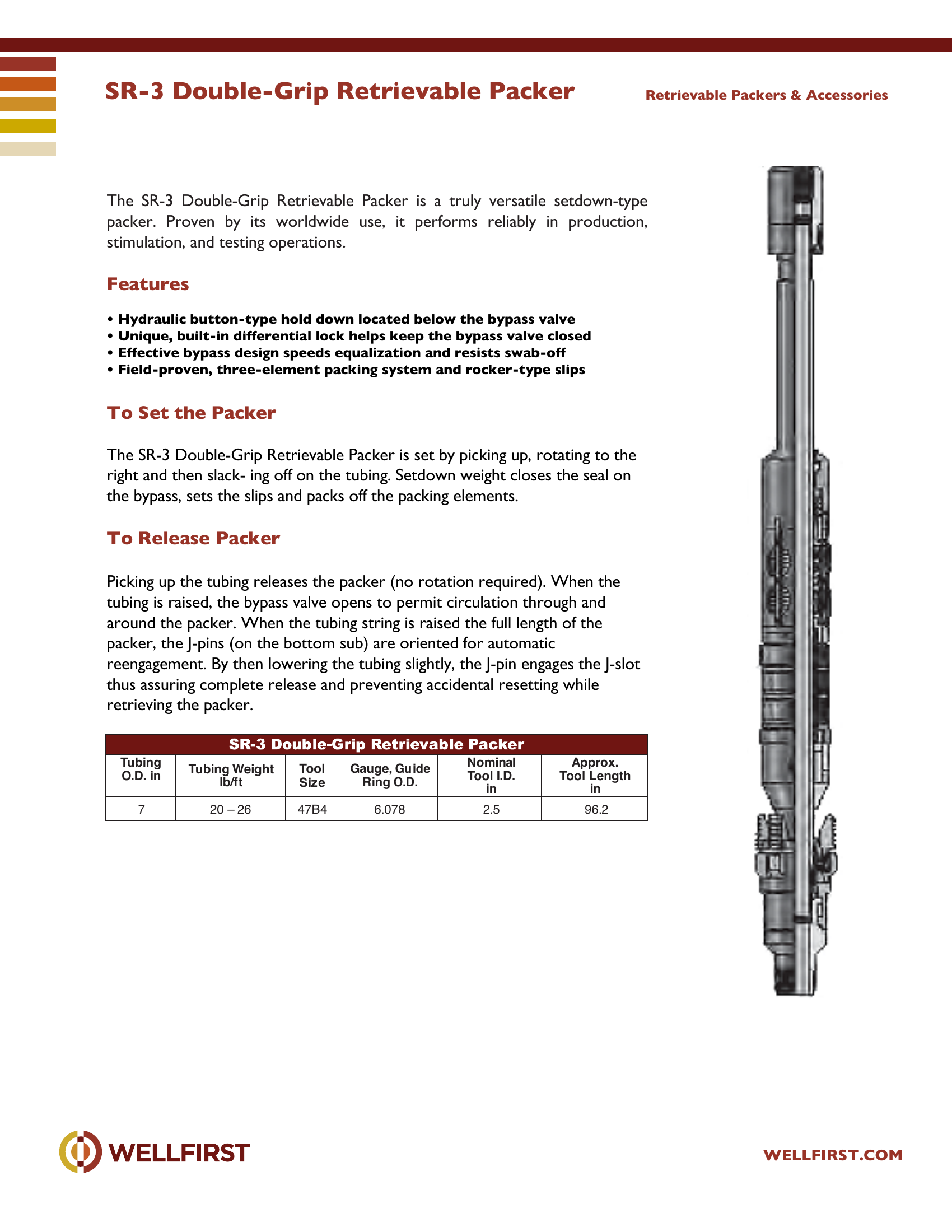
SR-3 Double-Grip Retrievable Packer The SR-3 Double-Grip Retrievable Packer is a truly versatile setdown-type packer. Proven by its worldwide use, it performs reliably in production, stimulation, and testing operations.

Key features
  • Hydraulic button-type hold down located below the bypass valve
  • Unique, built-in differential lock helps keep the bypass valve closed
  • Effective bypass design speeds equalization and resists swab-off
  • Field-proven, three-element packing system and rocker-type slips To Set the Packer The SR-3 Double-Grip Retrievable Packer is set by picking up, rotating to the right and then slack- ing off on the tubing. Setdown weight closes the seal on To Release Packer Picking up the tubing releases the packer (no rotation required). When the tubing is raised, the bypass valve opens to permit circulation through and around the packer. When the tubing string is raised the full length of the packer, the J-pins (on the bottom sub) are oriented for automatic reengagement. By then lowering the tubing slightly, the J-pin engages the J-slot thus assuring complete release and preventing accidental resetting while Retrievable Packers & Accessories Tubing lb/ft Tool Size Gauge, Gu ide Ring O.D. in Approx. in 7 20 – 26 47B4 6.078 2.5 96.2

Complete dimensional data, part numbering and setting procedures are in the PDF.
Completion Packers|•| 
Full data sheet (PDF)
Shear Set Shear Release Tension Packer

Shear Set Shear Release Tension Packer

PDF
Shear Set Shear Release Tension Packer

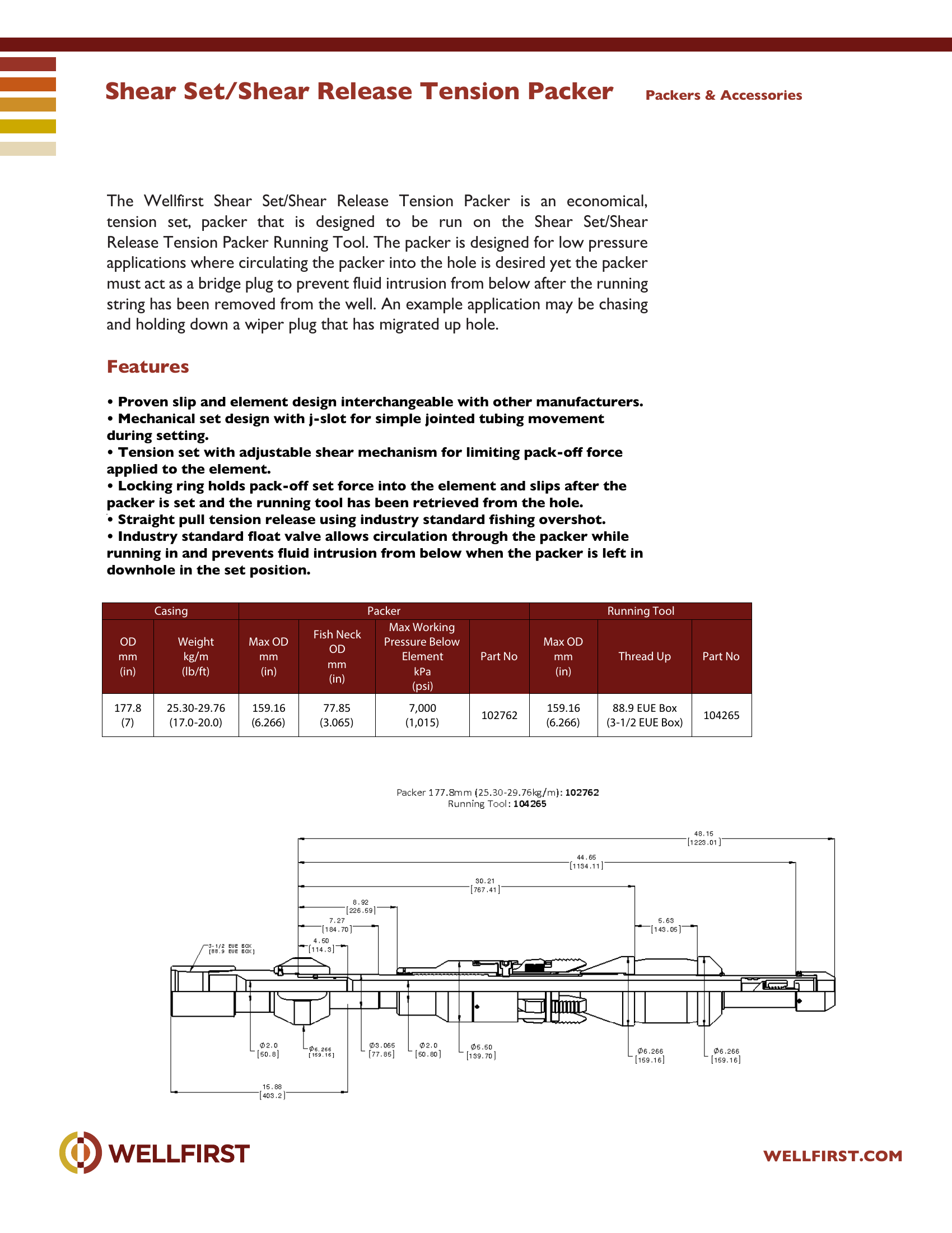
Shear Set/Shear Release Tension Packer The Wellfirst Shear Set/Shear Release Tension Packer is an economical, tension set, packer that is designed to be run on the Shear Set/Shear Release Tension Packer Running Tool. The packer is designed for low pressure applications where circulating the packer into the hole is desired yet the packer must act as a bridge plug to prevent fluid intrusion from below after the running string has been removed from the well. An example application may be chasing and holding down a wiper plug that has migrated up hole.

Key features
  • Proven slip and element design interchangeable with other manufacturers.
  • Mechanical set design with j-slot for simple jointed tubing movement
  • Tension set with adjustable shear mechanism for limiting pack-off force
  • Locking ring holds pack-off set force into the element and slips after the
  • Straight pull tension release using industry standard fishing overshot.
  • Industry standard float valve allows circulation through the packer while running in and prevents fluid intrusion from below when the packer is left in Packers & Accessories Casing Packer Running Tool OD mm (in) Weight kg/m (lb/ft) Max OD mm (in) Fish Neck OD mm (in) Max Working Pressure Below Element kPa (psi) Part No Max OD mm (in) Thread Up Part No 177.8 (7) 25.30-29.76 (17.0-20.0) 159.16 (6.266) 77.85 (3.065) 7,000 (1,015) 102762 159.16 (6.266) 88.9 EUE Box (3-1/2 EUE Box) 104265

Complete dimensional data, part numbering and setting procedures are in the PDF.
Completion Packers|•| 
Full data sheet (PDF)
Stage Stimulation Tool

Stage Stimulation Tool

PDF
Stage Stimulation Tool

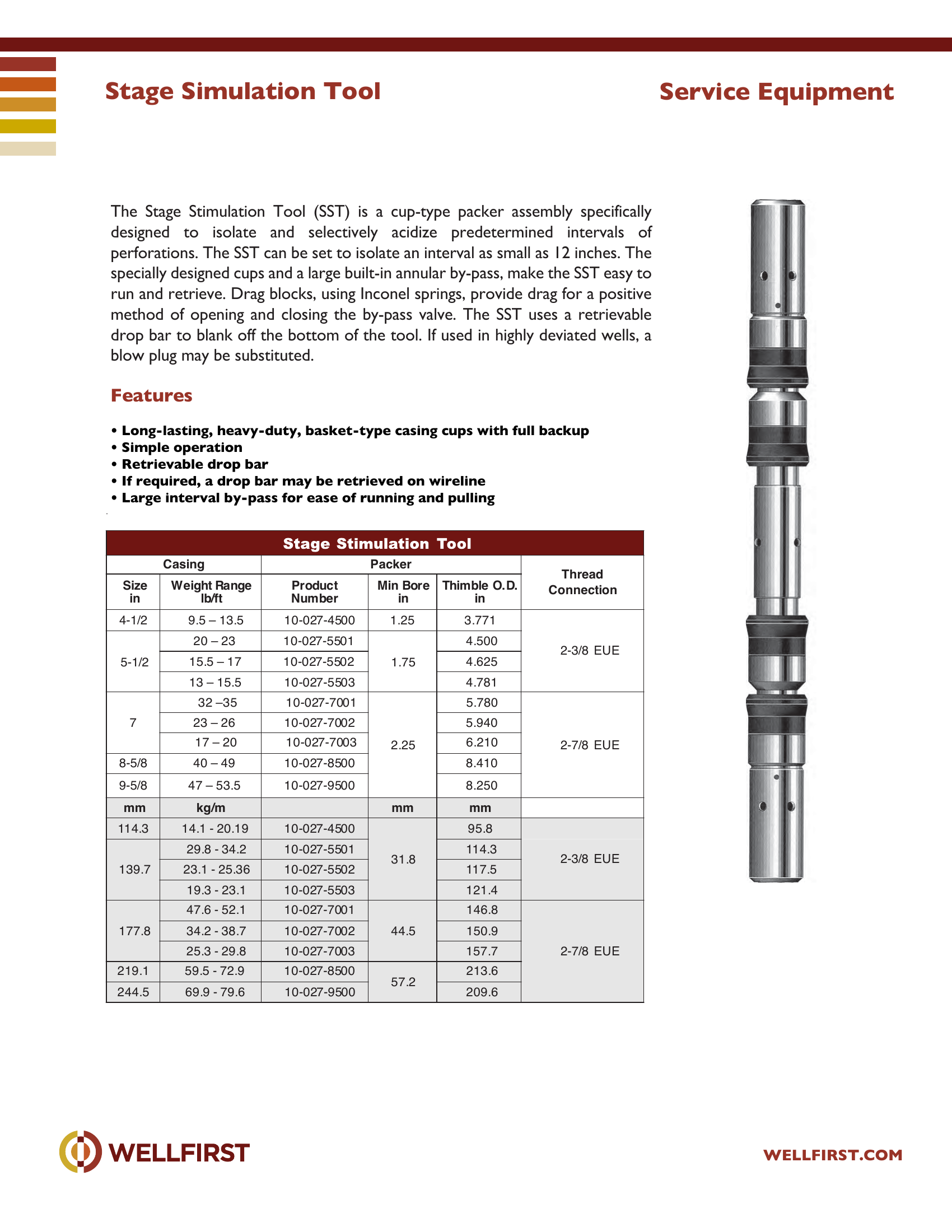
Stage Simulation Tool The Stage Stimulation Tool (SST) is a cup-type packer assembly specifically designed to isolate and selectively acidize predetermined intervals of perforations. The SST can be set to isolate an interval as small as 12 inches. The specially designed cups and a large built-in annular by-pass, make the SST easy to run and retrieve. Drag blocks, using Inconel springs, provide drag for a positive method of opening and closing the by-pass valve. The SST uses a retrievable drop bar to blank off the bottom of the tool. If used in highly deviated wells, a blow plug may be substituted.

Key features
  • Long-lasting, heavy-duty, basket-type casing cups with full backup
  • Simple operation
  • Retrievable drop bar
  • If required, a drop bar may be retrieved on wireline
  • Large interval by-pass for ease of running and pulling Service Equipment r e k c a P g n i s a C Thread Size in Weigh t Range lb/ft Product Number Min Bore in Thimble O.D. in Connection 4-1/2 9.5 – 13.5 10-027-4500 1.25 3. 771 5-1/2 20 – 23 10-027-5501 15.5 – 17 10-027-5502 1.75 4.50 0 4.625 2-3/8 EUE 13 – 15.5 10-027-5503 4.781 32 –35 10-027-7001 5.780 7 23 – 26 10-027-7002 5.940 17 – 20 10-027-7003 2.25 6.210 2-7/8 EUE 8-5/8 40 – 49 10-027-8500 8.410 9-5/8 47 – 53.5 10-027-9500 8.250 m m m m m / g k m m 114.3 14.1 - 20.19 10 -027-4500 95.8 139.7 29.8 - 34.2 10-027-5501 114.3 31.8 23.1 - 25.36 10-027-5502 117.5 19.3 - 23.1 10-027-5503 121.4 2-3/8 EUE 177.8 47.6 - 52.1 10-027-7001 34.2 - 38.7 10-027-7002 44.5 146.8 150.9 25 .3 - 29.8 10-027-7003 157.7 2-7/8 EUE 219.1 59.5 - 72.9 10-027-8500 57.2 213.6 244.5 69 .9 - 79.6 10-027-9500 209.6
Data sheet tables
Casing Size inWeight Range lb/ftPacker Product NumberMin Bore inThimble O.D. inThread Connection
4-1/29.5 – 13.510-027-45001.253.7712-3/8 EUE
5-1/220 – 2310-027-55011.754.500
15.5 – 1710-027-55024.625
13 – 15.510-027-55034.781
732 –3510-027-70012.255.7802-7/8 EUE
23 – 2610-027-70025.940
17 – 2010-027-70036.210
8-5/840 – 4910-027-85008.410
9-5/847 – 53.510-027-95008.250
114.314.1 - 20.1910-027-450031.895.8
139.729.8 - 34.210-027-5501114.32-3/8 EUE
23.1 - 25.3610-027-5502117.5
19.3 - 23.110-027-5503121.4
177.847.6 - 52.110-027-700144.5146.82-7/8 EUE
34.2 - 38.710-027-7002150.9
25.3 - 29.810-027-7003157.7
219.159.5 - 72.910-027-850057.2213.6
244.569.9 - 79.610-027-9500209.6

Complete dimensional data, part numbering and setting procedures are in the PDF.
Completion Packers|•| 
Full data sheet (PDF)
Straddle Packer Selective Acidizing Tool

Straddle Packer Selective Acidizing Tool

PDF
Straddle Packer Selective Acidizing Tool

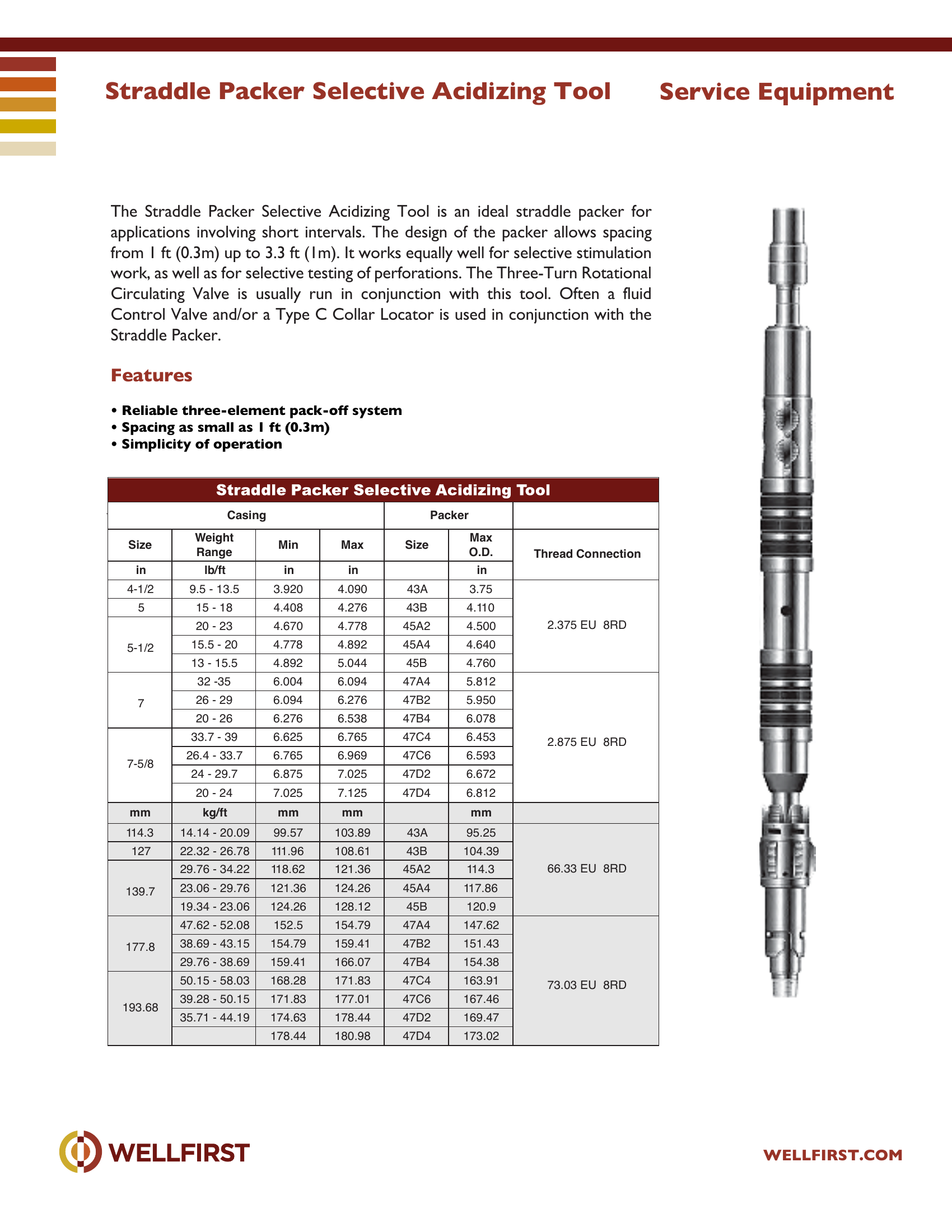
Straddle Packer Selective Acidizing Tool The Straddle Packer Selective Acidizing Tool is an ideal straddle packer for applications involving short intervals. The design of the packer allows spacing from 1 ft (0.3m) up to 3.3 ft (1m). It works equally well for selective stimulation work, as well as for selective testing of perforations. The Three-Turn Rotational Circulating Valve is usually run in conjunction with this tool. Often a fluid Control Valve and/or a Type C Collar Locator is used in conjunction with the Straddle Packer.

Key features
  • Reliable three-element pack-off system
  • Spacing as small as 1 ft (0.3m)
  • Simplicity of operation Service Equipment Casing Pac ker Size Weight Range Min Max Size Max . Thread Con nection in lb/ft in in in 4-1/2 9.5 - 13.5 3.920 4.090 43A 3.75 2.375 EU 8RD 5 15 - 18 4.408 4.276 43B 4.1 10 5-1/2 20 - 23 4.670 4.778 45A2 4.500 15.5 - 20 4.778 4.892 45A4 4.640 13 - 15.5 4.892 5.044 45B 4.760 7 32 -3 5 6.004 6.094 47A4 5.812 2.875 EU 8RD 26 - 29 6.094 6.276 47B2 5.950 20 - 26 6.276 6.538 47B4 6.078 7-5/8 33.7 - 39 6.625 6.765 47C4 6.453 26.4 - 33.7 6.765 6.969 47C6 6.593 24 - 29.7 6.875 7.025 47D2 6.672 20 - 24 7.025 7.125 47D4 6.812 mm kg/ft mm mm mm 114.3 14.14 - 20.09 99.57 103.89 43A 95.25 66.33 EU 8RD 127 22.32 - 26.78 111.96 108.61 43B 104.39 139.7 29.76 - 34.22 118.62 121.36 45A2 114.3 23.06 - 29.76 121.36 124.26 45A4 117.86 19.34 - 23.06 124.26 128.12 45B 120.9 177.8 47.62 - 52.08 152.5 154.79 47A4 147.62 73.03 EU 8RD 38.69 - 43.15 154.79 159.41 47B2 151.43 29.76 - 38.69 159.41 166.07 47B4 154.38 193.68 50.15 - 58.03 168.28 171.83 47C4 163.91 39.28 - 50.15 171.83 177.01 47C6 167.46 35.71 - 44.19 174.63 178.44 47D2 169.47 178.44 180.98 47D4 173.02
Data sheet tables
Casing Size inWeight Range lb/ftMin inMax inPacker SizeMax O.D. inThread Connection
4-1/29.5 - 13.53.9204.09043A3.752.375 EU 8RD
515 - 184.4084.27643B4.110
5-1/220 - 234.6704.77845A24.500
15.5 - 204.7784.89245A44.640
13 - 15.54.8925.04445B4.760
732 -356.0046.09447A45.8122.875 EU 8RD
26 - 296.0946.27647B25.950
20 - 266.2766.53847B46.078
7-5/833.7 - 396.6256.76547C46.453
26.4 - 33.76.7656.96947C66.593
24 - 29.76.8757.02547D26.672
20 - 247.0257.12547D46.812
mmkg/ftmmmmmm
114.314.14 - 20.0999.57103.8943A95.25
12722.32 - 26.78111.96108.6143B104.39
29.76 - 34.22118.62121.3645A2114.366.33 EU 8RD
23.06 - 29.76121.36124.2645A4117.86
139.7
19.34 - 23.06124.26128.1245B120.9
47.62 - 52.08152.5154.7947A4147.62
38.69 - 43.15154.79159.4147B2151.43
177.8
29.76 - 38.69159.41166.0747B4154.38
50.15 - 58.03168.28171.8347C4163.91
73.03 EU 8RD
39.28 - 50.15171.83177.0147C6167.46
193.68
35.71 - 44.19174.63178.4447D2169.47
178.44180.9847D4173.02

Complete dimensional data, part numbering and setting procedures are in the PDF.
Completion Packers|•| 
Full data sheet (PDF)
XT-2 Service Packer

XT-2 Service Packer

PDF
XT-2 Service Packer

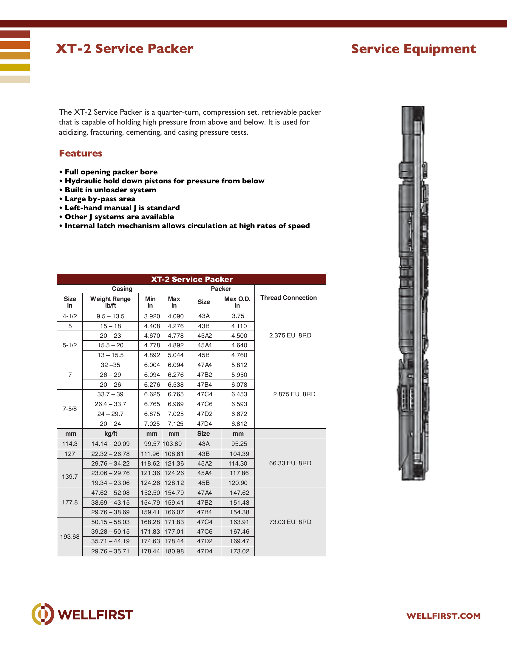
XT-2 Service Packer The XT-2 Service Packer is a quarter-turn, compression set, retrievable packer that is capable of holding high pressure from above and below. It is used for acidizing, fracturing, cementing, and casing pressure tests.

Key features
  • Full opening packer bore
  • Hydraulic hold down pistons for pressure from below
  • Built in unloader system
  • Large by-pass area
  • Left-hand manual J is standard
  • Other J systems are available
Data sheet tables
Casing Packer SizeWeight Range lb/ftMin inMax inSizeMax O.D. in
4-1/29.5 – 13.53.9204.09043A3.752.375 EU 8RD
515 – 184.4084.27643B4.110
5-1/220 – 234.6704.77845A24.500
15.5 – 204.7784.89245A44.640
13 – 15.54.8925.04445B4.760
732 –356.0046.09447A45.8122.875 EU 8RD
26 – 296.0946.27647B25.950
20 – 266.2766.53847B46.078
7-5/833.7 – 396.6256.76547C46.453
26.4 – 33.76.7656.96947C66.593
24 – 29.76.8757.02547D26.672
20 – 247.0257.12547D46.812
mmkg/ftmmmmSizemm
114.314.14 – 20.0999.57103.8943A95.25
12722.32 – 26.78111.96108.6143B104.39
29.76 – 34.22118.62121.3645A2114.3066.33 EU 8RD
23.06 – 29.76121.36124.2645A4117.86
139.719.34 – 23.06124.26128.1245B120.90
47.62 – 52.08152.50154.7947A4147.62
177.838.69 – 43.15154.79159.4147B2151.43
29.76 – 38.69159.41166.0747B4154.38
50.15 – 58.03168.28171.8347C4163.9173.03 EU 8RD
39.28 – 50.15171.83177.0147C6167.46
193.68
35.71 – 44.19174.63178.4447D2169.47
29.76 – 35.71178.44180.9847D4173.02

Complete dimensional data, part numbering and setting procedures are in the PDF.
Completion Packers|•| 
Full data sheet (PDF)