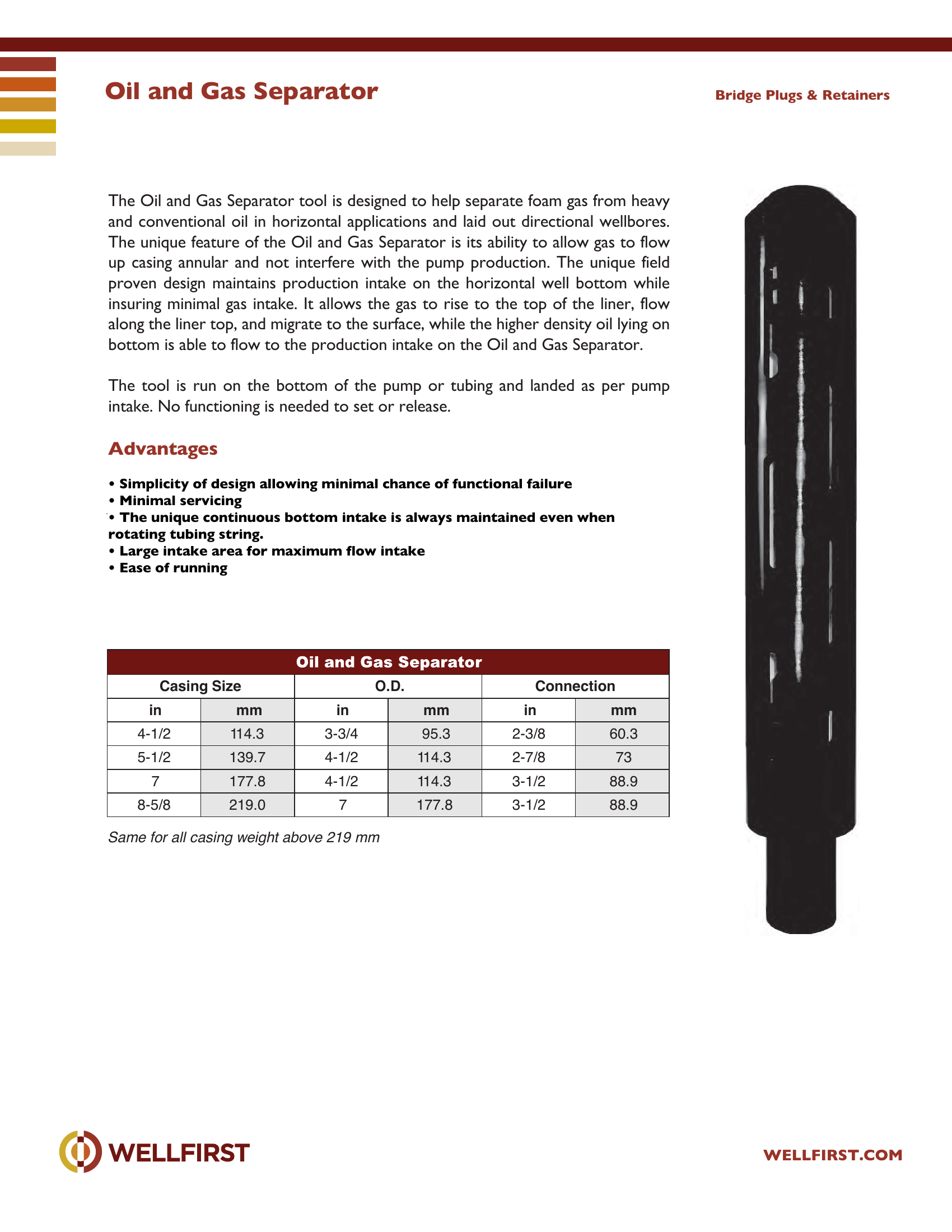
Oil and Gas Separator
The Oil and Gas Separator tool is designed to help separate foam gas from heavy and conventional oil in horizontal applications and laid out directional wellbores. The unique feature of the Oil and Gas Separator is its ability to allow gas to flow up casing annular and not interfere with the pump production. The unique field proven design maintains production intake on the horizontal well bottom while insuring minimal gas intake. It allows the gas to rise to the top of the liner, flow along the liner top, and migrate to the surface, while the higher density oil lying on bottom is able to flow to the production intake on the Oil and Gas Separator. The tool is run on the bottom of the pump or tubing and landed as per pump intake. No functioning is needed to set or release. Advantages • Simplicity of design allowing minimal chance of functional failure • Minimal servicing • The unique continuous bottom intake is always maintained even when rotating tubing string. • Large intake area for maximum flow intake • Ease of running Bridge Plugs & Retainers
Data sheet tables
| Casing Size O.D. Connection in | mm | in | mm | in | mm |
|---|
| 4-1/2 | 114.3 | 3-3/4 | 95.3 | 2-3/8 | 60.3 |
| 5-1/2 | 139.7 | 4-1/2 | 114.3 | 2-7/8 | 73 |
| 7 | 177.8 | 4-1/2 | 114.3 | 3-1/2 | 88.9 |
| 8-5/8 | 219.0 | 7 | 177.8 | 3-1/2 | 88.9 |
Complete dimensional data, part numbering and setting procedures are in the PDF.
Tubing Accessories|•|
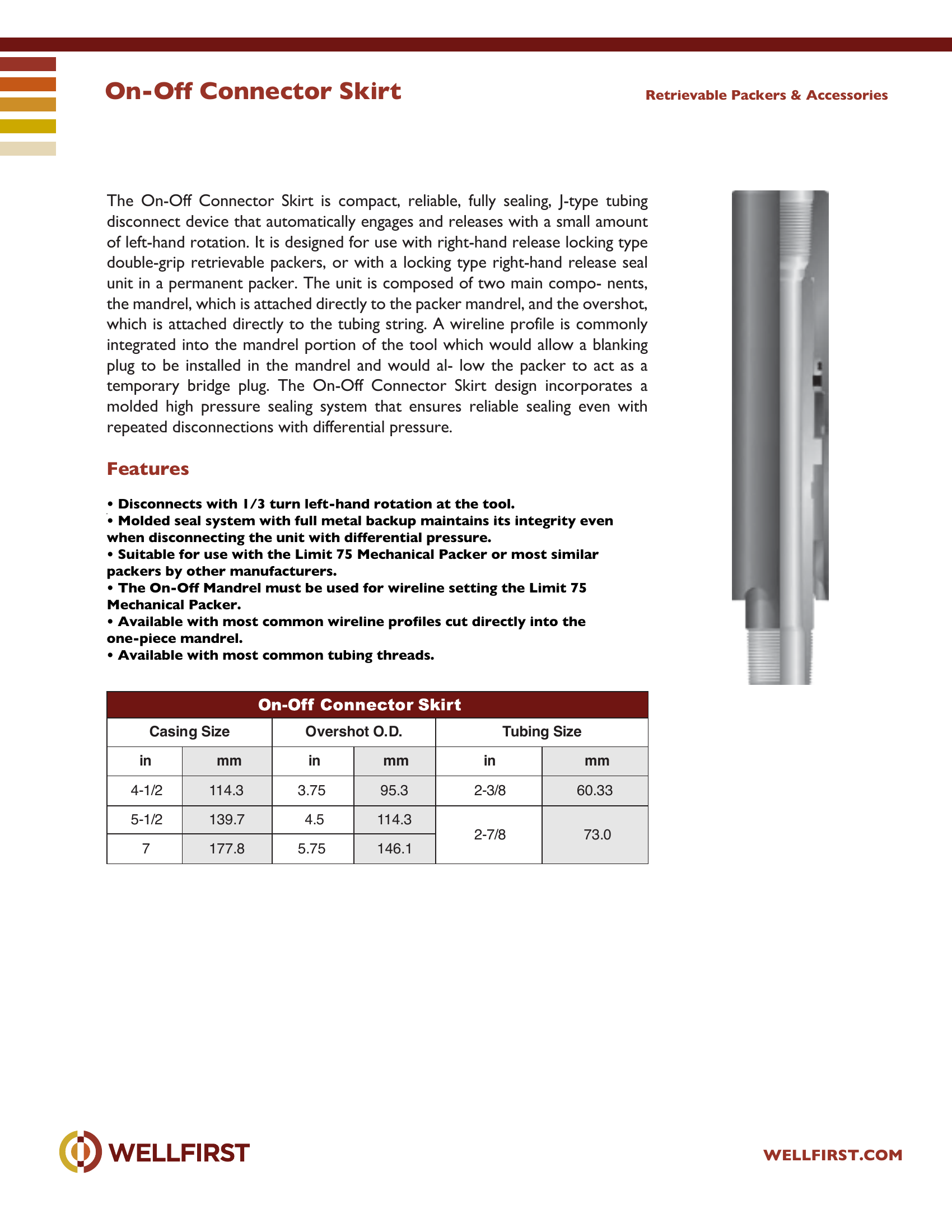
On-Off Connector Skirt
On-Off Connector Skirt The On-Off Connector Skirt is compact, reliable, fully sealing, J-type tubing disconnect device that automatically engages and releases with a small amount of left-hand rotation. It is designed for use with right-hand release locking type double-grip retrievable packers, or with a locking type right-hand release seal unit in a permanent packer. The unit is composed of two main compo- nents, the mandrel, which is attached directly to the packer mandrel, and the overshot, which is attached directly to the tubing string. A wireline profile is commonly integrated into the mandrel portion of the tool which would allow a blanking plug to be installed in the mandrel and would al- low the packer to act as a temporary bridge plug. The On-Off Connector Skirt design incorporates a molded high pressure sealing system that ensures reliable sealing even with repeated disconnections with differential pressure.
Key features
- Disconnects with 1/3 turn left-hand rotation at the tool.
- Molded seal system with full metal backup maintains its integrity even
- Suitable for use with the Limit 75 Mechanical Packer or most similar
- The On-Off Mandrel must be used for wireline setting the Limit 75 Mechanical Packer.
- Available with most common wireline profiles cut directly into the
- Available with most common tubing threads. in mm in mm in mm 4-1/2 114.3 3.75 95.3 2-3/8 60.33 5-1/2 139.7 4.5 114.3 2-7/8 73.0 7 177.8 5.75 146.1
Data sheet tables
| Casing Size in | mm | Overshot O.D. in | mm | Tubing Size in | mm |
|---|
| 4-1/2 | 114.3 | 3.75 | 95.3 | 2-3/8 | 60.33 |
| 5-1/2 | 139.7 | 4.5 | 114.3 | 2-7/8 | |
| | | | | 73.0 |
| 7 | 177.8 | 5.75 | 146.1 | | |
Complete dimensional data, part numbering and setting procedures are in the PDF.
Tubing Accessories|•|
Re-Entry Guide
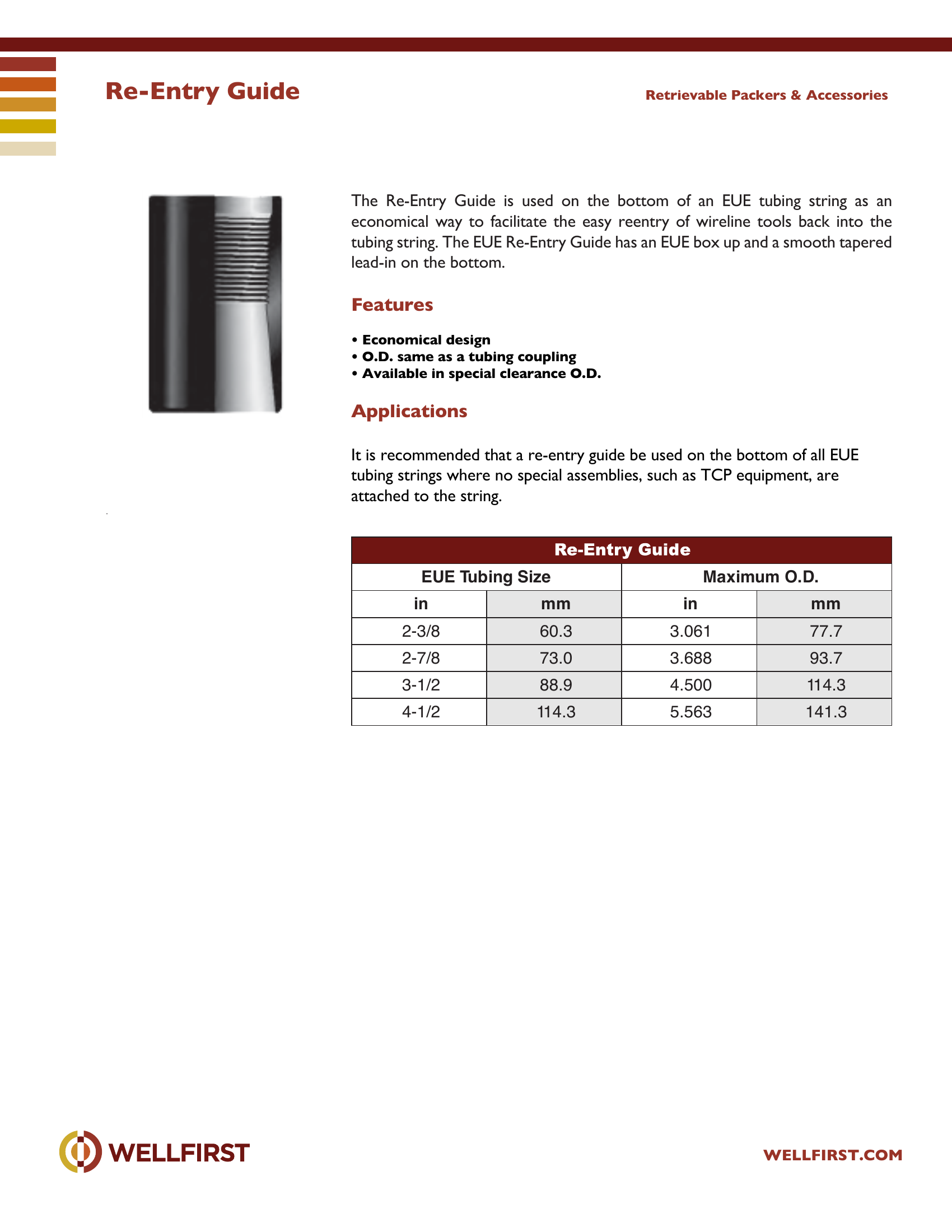
Re-Entry Guide The Re-Entry Guide is used on the bottom of an EUE tubing string as an economical way to facilitate the easy reentry of wireline tools back into the tubing string. The EUE Re-Entry Guide has an EUE box up and a smooth tapered lead-in on the bottom.
Key features
- Economical design
- O.D. same as a tubing coupling
- Available in special clearance O.D. tubing strings where no special assemblies, such as TCP equipment, are Retrievable Packers & Accessories EUE T ubing Size Maximum O.D. in mm in mm 2-3/8 60.3 3.061 77.7 2-7/8 73.0 3.688 93.7 3-1/2 88.9 4.500 114.3 4-1/2 114.3 5.563 141.3
Data sheet tables
| EUE Tubing Size in | mm | Maximum O.D. in | mm |
|---|
| 2-3/8 | 60.3 | 3.061 | 77.7 |
| 2-7/8 | 73.0 | 3.688 | 93.7 |
| 3-1/2 | 88.9 | 4.500 | 114.3 |
| 4-1/2 | 114.3 | 5.563 | 141.3 |
Complete dimensional data, part numbering and setting procedures are in the PDF.
Tubing Accessories|•|
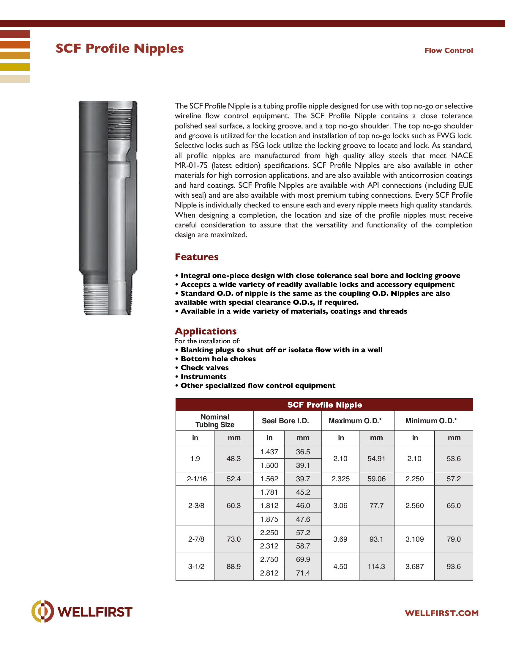
SCF Profile Nipples
SCF Profile Nipples The SCF Profile Nipple is a tubing profile nipple designed for use with top no-go or selective wireline flow control equipment. The SCF Profile Nipple contains a close tolerance polished seal surface, a locking groove, and a top no-go shoulder. The top no-go shoulder and groove is utilized for the location and installation of top no-go locks such as FWG lock. Selective locks such as FSG lock utilize the locking groove to locate and lock. As standard, all profile nipples are manufactured from high quality alloy steels that meet NACE MR-01-75 (latest edition) specifications. SCF Profile Nipples are also available in other materials for high corrosion applications, and are also available with anticorrosion coatings and hard coatings. SCF Profile Nipples are available with API connections (including EUE with seal) and are also available with most premium tubing connections. Every SCF Profile Nipple is individually checked to ensure each and every nipple meets high quality standards. When designing a completion, the location and size of the profile nipples must receive careful consideration to assure that the versatility and functionality of the completion design are maximized.
Key features
- Integral one-piece design with close tolerance seal bore and locking groove
- Accepts a wide variety of readily available locks and accessory equipment
- Standard O.D. of nipple is the same as the coupling O.D. Nipples are also
- Available in a wide variety of materials, coatings and threads Applications For the installation of:
- Blanking plugs to shut off or isolate flow with in a well
- Bottom hole chokes
Data sheet tables
| Nominal Seal Bore | mm | in | mm | in | mm | in | mm |
|---|
| 1.9 | | 1.437 | 36.5 | 2.10 | | 2.10 | |
| 48.3 | | | | 54.91 | | 53.6 |
| | 1.500 | 39.1 | | | | |
| 2-1/16 | 52.4 | 1.562 | 39.7 | 2.325 | 59.06 | 2.250 | 57.2 |
| 2-3/8 | | 1.781 | 45.2 | 3.06 | | 2.560 | |
| 60.3 | 1.812 | 46.0 | | 77.7 | | 65.0 |
| | 1.875 | 47.6 | | | | |
| 2-7/8 | | 2.250 | 57.2 | 3.69 | | 3.109 | |
| 73.0 | | | | 93.1 | | 79.0 |
| | 2.312 | 58.7 | | | | |
| 3-1/2 | | 2.750 | 69.9 | 4.50 | | 3.687 | |
| 88.9 | | | | 114.3 | | 93.6 |
| | 2.812 | 71.4 | | | | |
Complete dimensional data, part numbering and setting procedures are in the PDF.
Tubing Accessories|•|
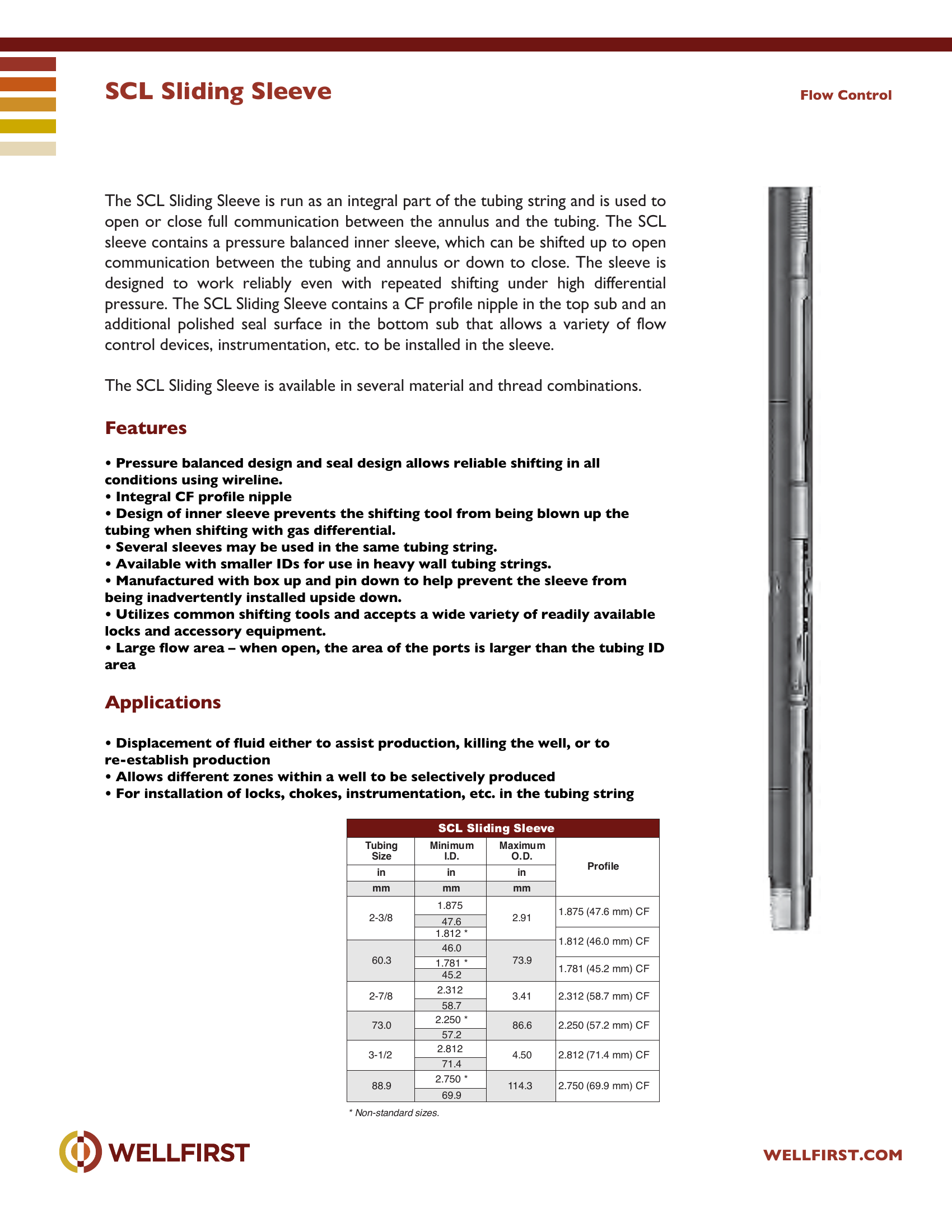
SCL Sliding Sleeve
SCL Sliding Sleeve The SCL Sliding Sleeve is run as an integral part of the tubing string and is used to open or close full communication between the annulus and the tubing. The SCL sleeve contains a pressure balanced inner sleeve, which can be shifted up to open communication between the tubing and annulus or down to close. The sleeve is designed to work reliably even with repeated shifting under high differential pressure. The SCL Sliding Sleeve contains a CF profile nipple in the top sub and an additional polished seal surface in the bottom sub that allows a variety of flow control devices, instrumentation, etc. to be installed in the sleeve. The SCL Sliding Sleeve is available in several material and thread combinations.
Key features
- Pressure balanced design and seal design allows reliable shifting in all
- Integral CF profile nipple
- Design of inner sleeve prevents the shifting tool from being blown up the
- Several sleeves may be used in the same tubing string.
- Available with smaller IDs for use in heavy wall tubing strin
- Manufactured with box up and pin down to help prevent the sleeve from
Data sheet tables
| Tubing Size in mm | Minimum I.D. in mm | Maximum O.D. in mm | Profile |
|---|
| 2-3/8 | 1.875 | 2.91 | 1.875 (47.6 mm) CF |
| 47.6 | | |
| 1.812 * | | 1.812 (46.0 mm) CF |
| 46.0 | | |
| 60.3 | 1.781 * | 73.9 | 1.781 (45.2 mm) CF |
| 45.2 | | |
| 2-7/8 | 2.312 | 3.41 | 2.312 (58.7 mm) CF |
| 58.7 | | |
| 2.250 * | | 2.250 (57.2 mm) CF |
| 73.0 | | 86.6 | |
| 57.2 | | |
| 3-1/2 | 2.812 | 4.50 | 2.812 (71.4 mm) CF |
| 71.4 | | |
| 2.750 * | | 2.750 (69.9 mm) CF |
| 88.9 | | 114.3 | |
| 69.9 | | |
Complete dimensional data, part numbering and setting procedures are in the PDF.
Tubing Accessories|•|
SCR Profile Nipples
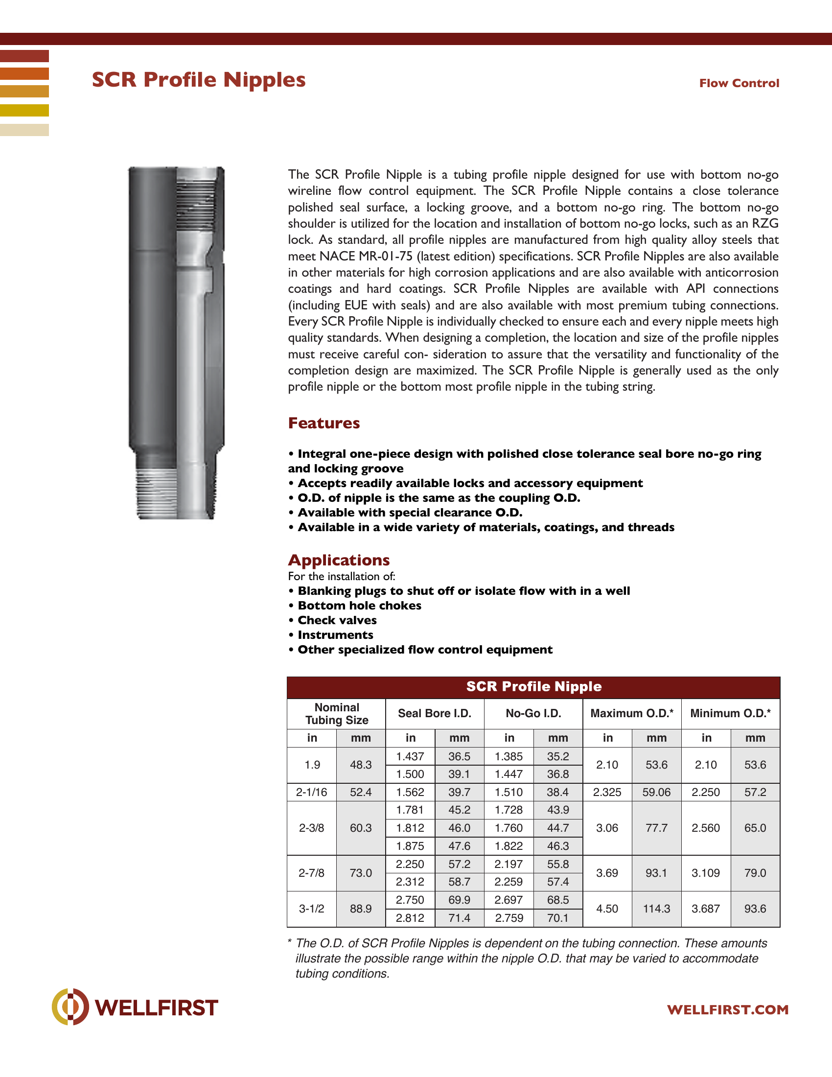
SCR Profile Nipples The SCR Profile Nipple is a tubing profile nipple designed for use with bottom no-go wireline flow control equipment. The SCR Profile Nipple contains a close tolerance polished seal surface, a locking groove, and a bottom no-go ring. The bottom no-go shoulder is utilized for the location and installation of bottom no-go locks, such as an RZG lock. As standard, all profile nipples are manufactured from high quality alloy steels that meet NACE MR-01-75 (latest edition) specifications. SCR Profile Nipples are also available in other materials for high corrosion applications and are also available with anticorrosion coatings and hard coatings. SCR Profile Nipples are available with API connections (including EUE with seals) and are also available with most premium tubing connections. Every SCR Profile Nipple is individually checked to ensure each and every nipple meets high quality standards. When designing a completion, the location and size of the profile nipples must receive careful con- sideration to assure that the versatility and functionality of the completion design are maximized. The SCR Profile Nipple is generally used as the only profile nipple or the bottom most profile nipple in the tubing string.
Key features
- Integral one-piece design with polished close tolerance seal bore no-go ring and locking groove
- Accepts readily available locks and accessory equipment
- O.D. of nipple is the same as the coupling O.D.
- Available with special clearance O.D.
- Available in a wide variety of materials, coatings, and threa ds Applications For the installation of:
- Blanking plugs to shut off or isolate flow with in a well
Data sheet tables
| Nominal Tubing Size in | mm | Seal Bore I.D. in | mm | No-Go I.D. in | mm | Maximum O.D.* in | mm | Minimum O.D.* in | mm |
|---|
| 1.9 | | 1.437 | 36.5 | 1.385 | 35.2 | 2.10 | | 2.10 | |
| 48.3 | | | | | | 53.6 | | 53.6 |
| | 1.500 | 39.1 | 1.447 | 36.8 | | | | |
| 2-1/16 | 52.4 | 1.562 | 39.7 | 1.510 | 38.4 | 2.325 | 59.06 | 2.250 | 57.2 |
| 2-3/8 | | 1.781 | 45.2 | 1.728 | 43.9 | 3.06 | | 2.560 | |
| 60.3 | 1.812 | 46.0 | 1.760 | 44.7 | | 77.7 | | 65.0 |
| | 1.875 | 47.6 | 1.822 | 46.3 | | | | |
| 2-7/8 | | 2.250 | 57.2 | 2.197 | 55.8 | 3.69 | | 3.109 | |
| 73.0 | | | | | | 93.1 | | 79.0 |
| | 2.312 | 58.7 | 2.259 | 57.4 | | | | |
| 3-1/2 | | 2.750 | 69.9 | 2.697 | 68.5 | 4.50 | | 3.687 | |
| 88.9 | | | | | | 114.3 | | 93.6 |
| | 2.812 | 71.4 | 2.759 | 70.1 | | | | |
Complete dimensional data, part numbering and setting procedures are in the PDF.
Tubing Accessories|•|
SCX Profile Nipples
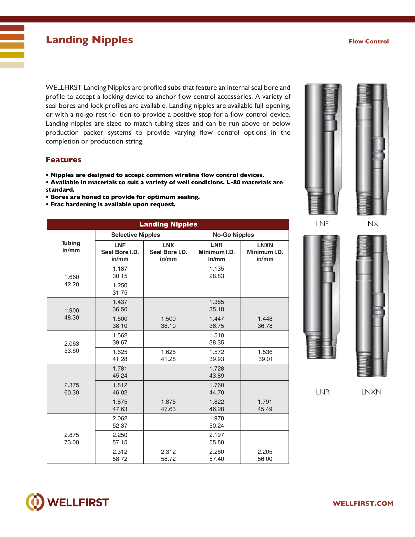
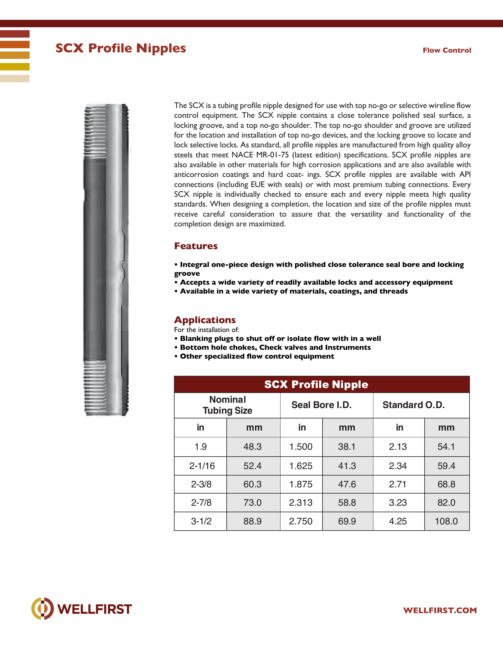
SCX Profile Nipples The SCX is a tubing profile nipple designed for use with top no-go or selective wireline flow control equipment. The SCX nipple contains a close tolerance polished seal surface, a locking groove, and a top no-go shoulder. The top no-go shoulder and groove are utilized for the location and installation of top no-go devices, and the locking groove to locate and lock selective locks. As standard, all profile nipples are manufactured from high quality alloy steels that meet NACE MR-01-75 (latest edition) specifications. SCX profile nipples are also available in other materials for high corrosion applications and are also available with anticorrosion coatings and hard coat- ings. SCX profile nipples are available with API connections (including EUE with seals) or with most premium tubing connections. Every SCX nipple is individually checked to ensure each and every nipple meets high quality standards. When designing a completion, the location and size of the profile nipples must receive careful consideration to assure that the versatility and functionality of the completion design are maximized.
Key features
- Integral one-piece design with polished close tolerance seal bore and locking groove
- Accepts a wide variety of readily available locks and accesso ry equipment
- Available in a wide variety of materials, coatings, and threa ds Applications For the installation of:
- Blanking plugs to shut off or isolate flow with in a well
- Bottom hole chokes, Check valves and Instruments
- Other specialized flow control equipment Flow Control Nominal Tubing Size Seal Bore I.D. Sta nd ard O.D. in mm in mm in mm 1.9 48.3 1.500 38.1 2.13 54.1 2-1/16 52.4 1.625 41.3 2.34 59.4 2-3/8 60.3 1.875 47.6 2.71 68.8 2-7/8 73.0 2.313 58.8 3.23 82.0 3-1/2 88.9 2.750 69.9 4.25 108.0
Data sheet tables
| Nominal Seal Bore | mm | in | mm | in | mm |
|---|
| 1.9 | 48.3 | 1.500 | 38.1 | 2.13 | 54.1 |
| 2-1/16 | 52.4 | 1.625 | 41.3 | 2.34 | 59.4 |
| 2-3/8 | 60.3 | 1.875 | 47.6 | 2.71 | 68.8 |
| 2-7/8 | 73.0 | 2.313 | 58.8 | 3.23 | 82.0 |
| 3-1/2 | 88.9 | 2.750 | 69.9 | 4.25 | 108.0 |
Complete dimensional data, part numbering and setting procedures are in the PDF.
Tubing Accessories|•|
SCXN Profile Nipples
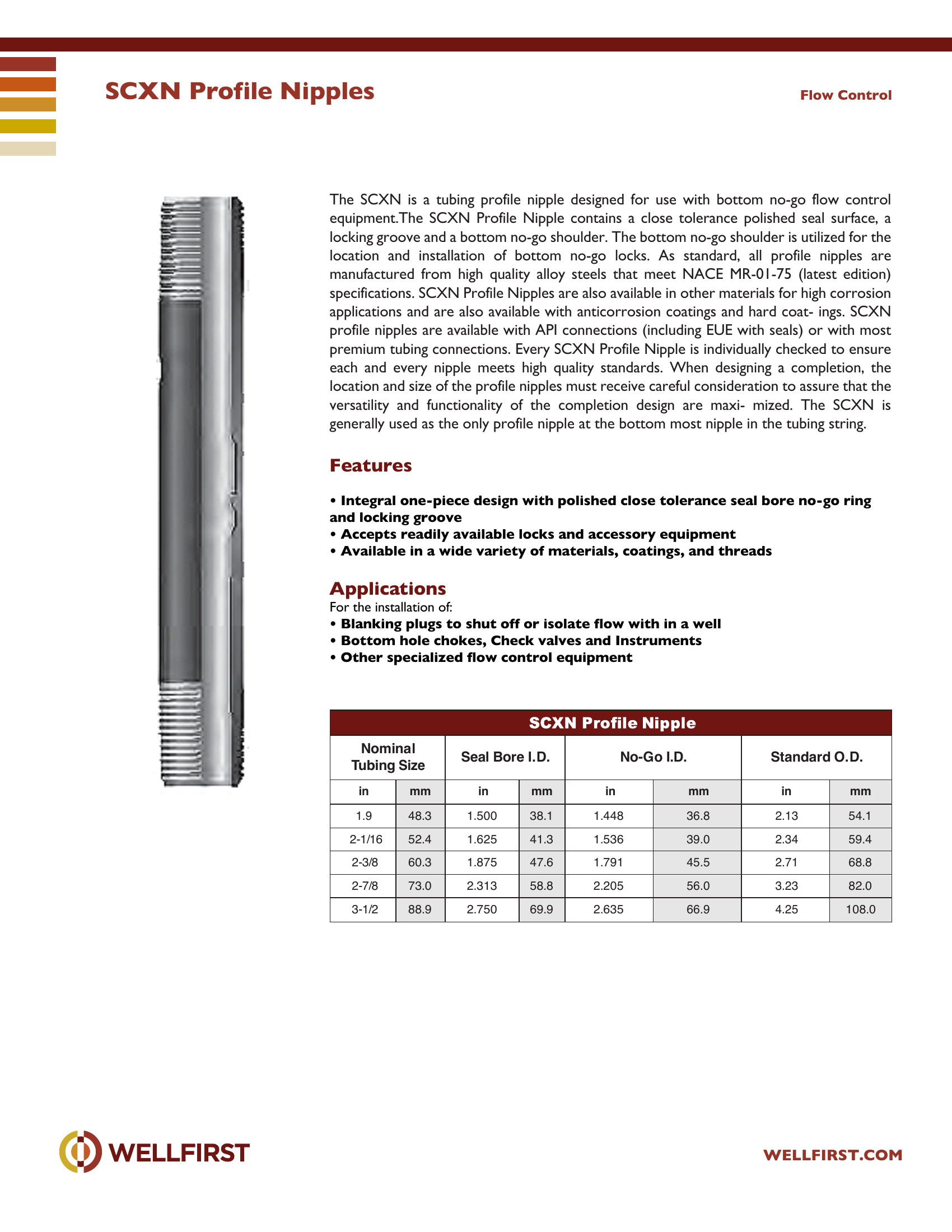
SCXN Profile Nipples The SCXN is a tubing profile nipple designed for use with bottom no-go flow control equipment.The SCXN Profile Nipple contains a close tolerance polished seal surface, a locking groove and a bottom no-go shoulder. The bottom no-go shoulder is utilized for the location and installation of bottom no-go locks. As standard, all profile nipples are manufactured from high quality alloy steels that meet NACE MR-01-75 (latest edition) specifications. SCXN Profile Nipples are also available in other materials for high corrosion applications and are also available with anticorrosion coatings and hard coat- ings. SCXN profile nipples are available with API connections (including EUE with seals) or with most premium tubing connections. Every SCXN Profile Nipple is individually checked to ensure each and every nipple meets high quality standards. When designing a completion, the location and size of the profile nipples must receive careful consideration to assure that the versatility and functionality of the completion design are maxi- mized. The SCXN is generally used as the only profile nipple at the bottom most nipple in the tubing string.
Key features
- Integral one-piece design with polished close tolerance seal bore no-go ring and locking groove
- Accepts readily available locks and accessory equipment
- Available in a wide variety of materials, coatings, and threa ds Applications For the installation of:
- Blanking plugs to shut off or isolate flow with in a well
- Bottom hole chokes, Check valves and Instruments
- Other specialized flow control equipment Flow Control Nominal Tubing Size Seal Bore I.D. No-Go I.D. Stand ard O.D. in mm in mm in mm in mm 1.9 48.3 1. 50 0 38.1 1. 44 8 36.8 2.13 54.1 2-1/16 52.4 1. 62 5 41.3 1. 53 6 39.0 2.34 59.4 2-3/8 60.3 1. 87 5 47.6 1. 79 1 45.5 2.71 68.8 2-7/8 73.0 2. 31 3 58.8 2. 20 5 56.0 3.23 82.0 3-1/2 88.9 2. 75 0 69.9 2. 63 5 66.9 4.25 108.0
Data sheet tables
| Nominal Seal Bore | mm | in | mm | in | mm | in | mm |
|---|
| 1.9 | 48.3 | 1.500 | 38.1 | 1.448 | 36.8 | 2.13 | 54.1 |
| 2-1/16 | 52.4 | 1.625 | 41.3 | 1.536 | 39.0 | 2.34 | 59.4 |
| 2-3/8 | 60.3 | 1.875 | 47.6 | 1.791 | 45.5 | 2.71 | 68.8 |
| 2-7/8 | 73.0 | 2.313 | 58.8 | 2.205 | 56.0 | 3.23 | 82.0 |
| 3-1/2 | 88.9 | 2.750 | 69.9 | 2.635 | 66.9 | 4.25 | 108.0 |
Complete dimensional data, part numbering and setting procedures are in the PDF.
Tubing Accessories|•|
SXCA Sliding Sleeve
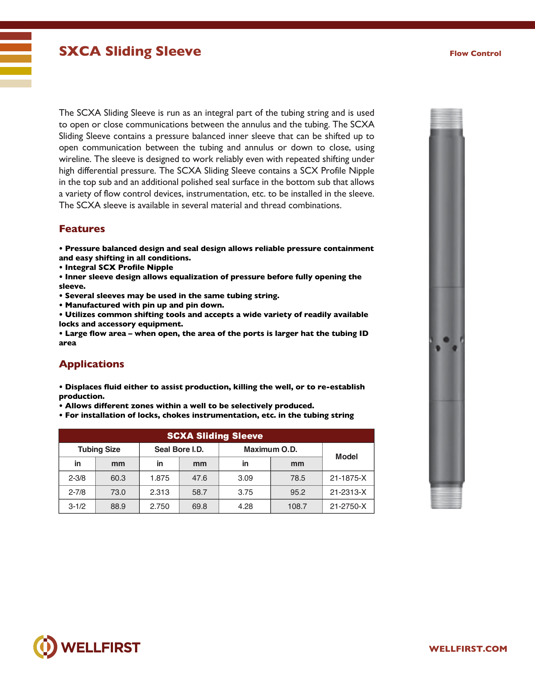
SXCA Sliding Sleeve The SCXA Sliding Sleeve is run as an integral part of the tubing string and is used to open or close communications between the annulus and the tubing. The SCXA Sliding Sleeve contains a pressure balanced inner sleeve that can be shifted up to open communication between the tubing and annulus or down to close, using wireline. The sleeve is designed to work reliably even with repeated shifting under high differential pressure. The SCXA Sliding Sleeve contains a SCX Profile Nipple in the top sub and an additional polished seal surface in the bottom sub that allows a variety of flow control devices, instrumentation, etc. to be installed in the sleeve. The SCXA sleeve is available in several material and thread combinations.
Key features
- Pressure balanced design and seal design allows reliable pressure containment
- Integral SCX Profile Nipple
- Several sleeves may be used in the same tubing string.
- Utilizes common shifting tools and accepts a wide variety of readily available
Data sheet tables
| Tubing Size in | mm | Seal Bore I.D. in | mm | Maximum O.D. in | mm | Model |
|---|
| 2-3/8 | 60.3 | 1.875 | 47.6 | 3.09 | 78.5 | 21-1875-X |
| 2-7/8 | 73.0 | 2.313 | 58.7 | 3.75 | 95.2 | 21-2313-X |
| 3-1/2 | 88.9 | 2.750 | 69.8 | 4.28 | 108.7 | 21-2750-X |
Complete dimensional data, part numbering and setting procedures are in the PDF.
Tubing Accessories|•|
Tubing Drain
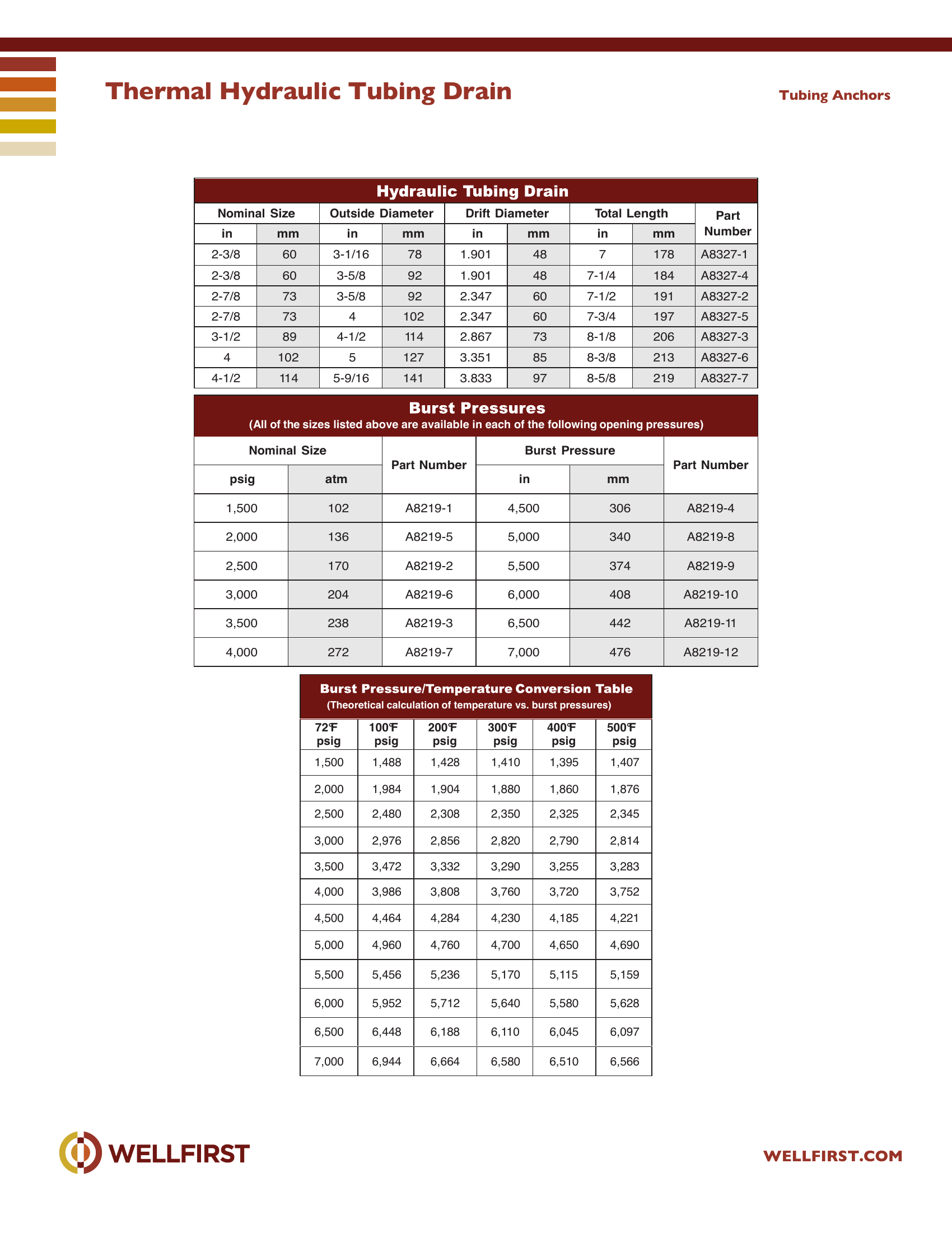
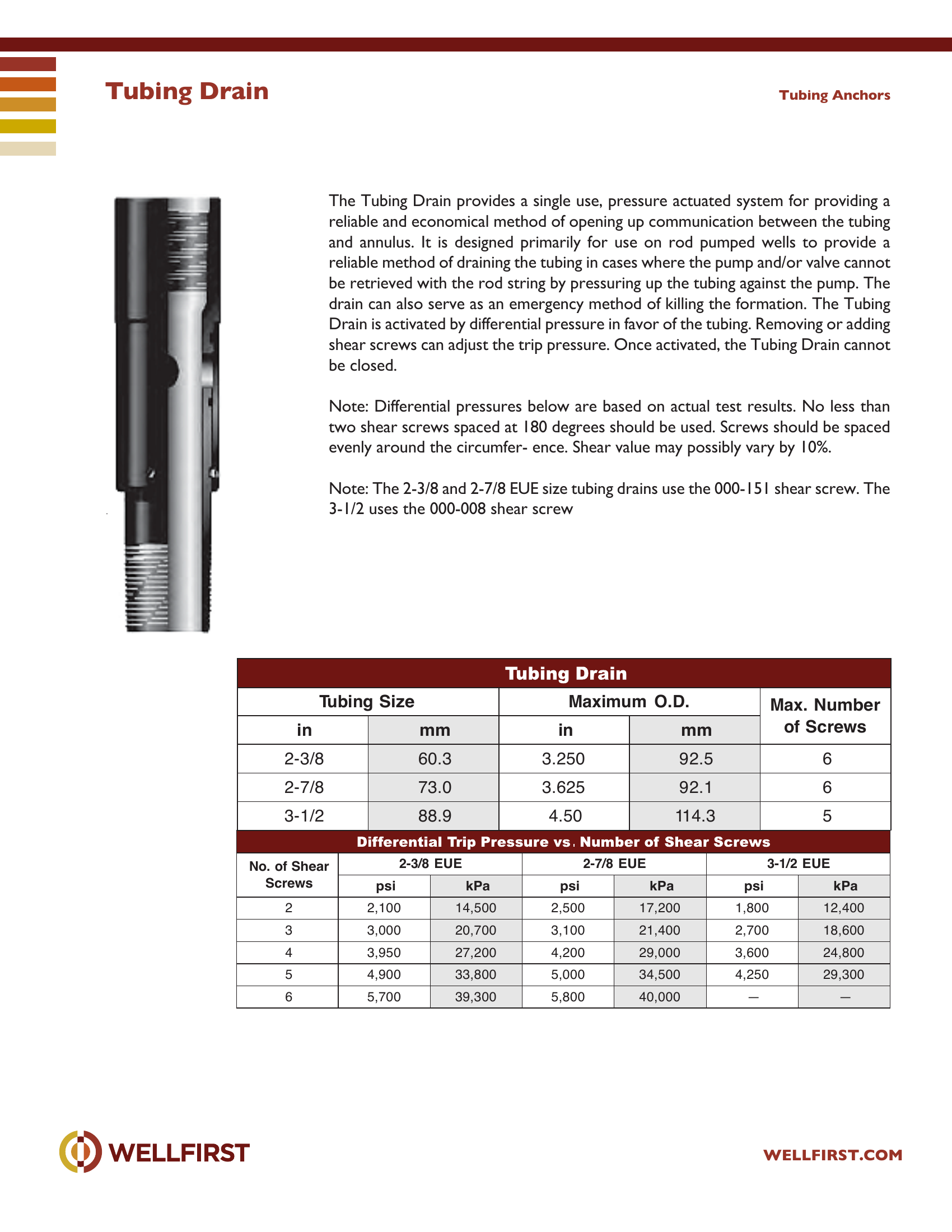
The Tubing Drain provides a single use, pressure actuated system for providing a reliable and economical method of opening up communication between the tubing and annulus. It is designed primarily for use on rod pumped wells to provide a reliable method of draining the tubing in cases where the pump and/or valve cannot be retrieved with the rod string by pressuring up the tubing against the pump. The drain can also serve as an emergency method of killing the formation. The Tubing Drain is activated by differential pressure in favor of the tubing. Removing or adding shear screws can adjust the trip pressure. Once activated, the Tubing Drain cannot be closed. Note: Differential pressures below are based on actual test results. No less than two shear screws spaced at 180 degrees should be used. Screws should be spaced evenly around the circumfer- ence. Shear value may possibly vary by 10%. Note: The 2-3/8 and 2-7/8 EUE size tubing drains use the 000-151 shear screw. The 3-1/2 uses the 000-008 shear screw Tubing Anchors Tubing Size Maximum O.D.
Data sheet tables
| Tubing Size in | | mm | | Maximum O.D. in | | mm | | Max. Number of Screws | |
|---|
| 2-3/8 | | 60.3 | | 3.250 | | 92.5 | | 6 | |
| 2-7/8 | | 73.0 | | 3.625 | | 92.1 | | 6 | |
| 3-1/2 | | 88.9 | | 4.50 | | 114.3 | | 5 | |
| No. of Shear 2-3/8 EUE 2-7/8 EUE 3-1/2 EUE Screws psi kPa psi kPa psi kPa |
|---|
| 2 | 2,100 | | 14,500 | | 2,500 | 17,200 | 1,800 | | 12,400 |
| 3 | 3,000 | | 20,700 | | 3,100 | 21,400 | 2,700 | | 18,600 |
| 4 | 3,950 | | 27,200 | | 4,200 | 29,000 | 3,600 | | 24,800 |
| 5 | 4,900 | | 33,800 | | 5,000 | 34,500 | 4,250 | | 29,300 |
| 6 | 5,700 | | 39,300 | | 5,800 | 40,000 | — | | — |
Complete dimensional data, part numbering and setting procedures are in the PDF.
Tubing Accessories|•|
Tubing Pump-Out Plug
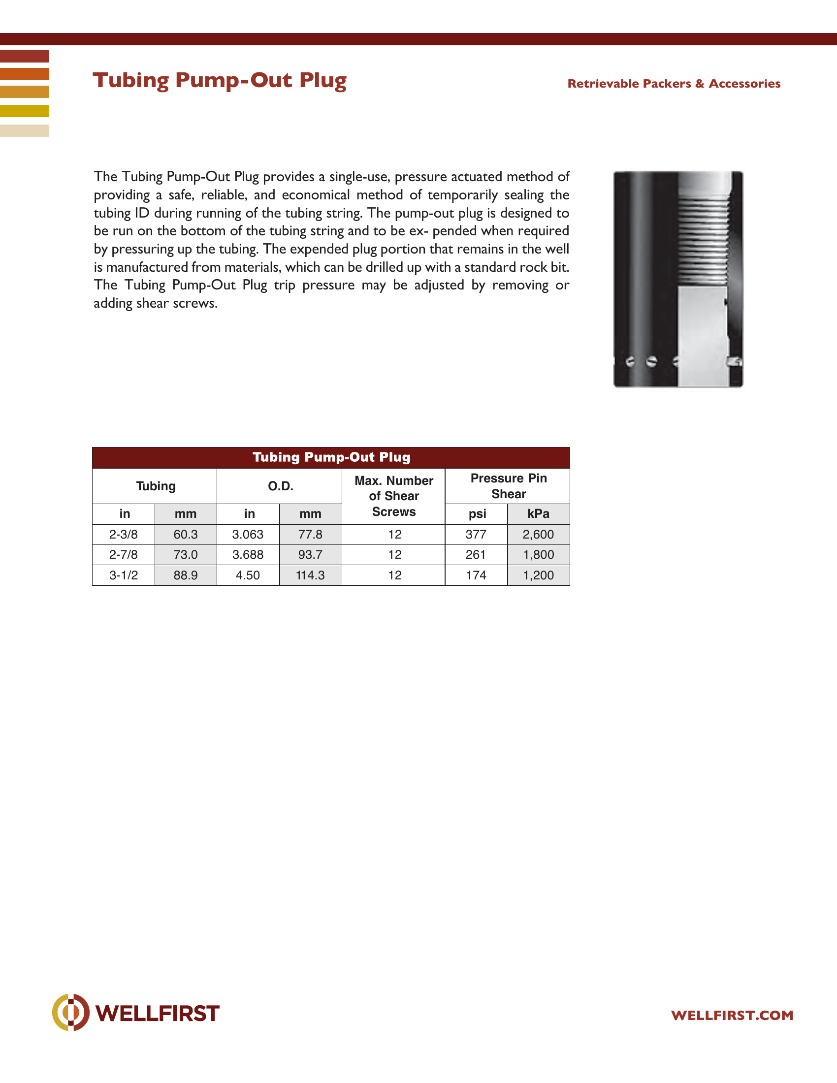
The Tubing Pump-Out Plug provides a single-use, pressure actuated method of providing a safe, reliable, and economical method of temporarily sealing the tubing ID during running of the tubing string. The pump-out plug is designed to be run on the bottom of the tubing string and to be ex- pended when required by pressuring up the tubing. The expended plug portion that remains in the well is manufactured from materials, which can be drilled up with a standard rock bit. The Tubing Pump-Out Plug trip pressure may be adjusted by removing or adding shear screws. Retrievable Packers & Accessories Tubing O.D. Max.
Data sheet tables
| Max. Number Pressure | mm | in | mm | | psi | kPa |
|---|
| 2-3/8 | 60.3 | 3.063 | 77.8 | 12 | 377 | 2,600 |
| 2-7/8 | 73.0 | 3.688 | 93.7 | 12 | 261 | 1,800 |
| 3-1/2 | 88.9 | 4.50 | 114.3 | 12 | 174 | 1,200 |
Complete dimensional data, part numbering and setting procedures are in the PDF.
Tubing Accessories|•|