
Wellfirst

WELLFIRST | a greater focus

PRODUCTS & SERVICES

Bridge Plugs

Wellfirst bridge plugs deliver dependable zonal isolation for testing, stimulation and temporary or permanent abandonment work. Mechanically and hydraulically set models span the full range of casing programs.

Applications

Stage isolation for plug-then-perf fracturing, cement retainers, temporary testing and abandonment.

Drillability

Composite and retrievable options balance set-time economics with removal effort.

Technical depth

Printable per-product sheets summarise ratings and features; the linked PDF carries the full data tables.

Bridge Plugs — 11 products

BD Cement Retainer

BD Cement Retainer

PDF
BD Cement Retainer

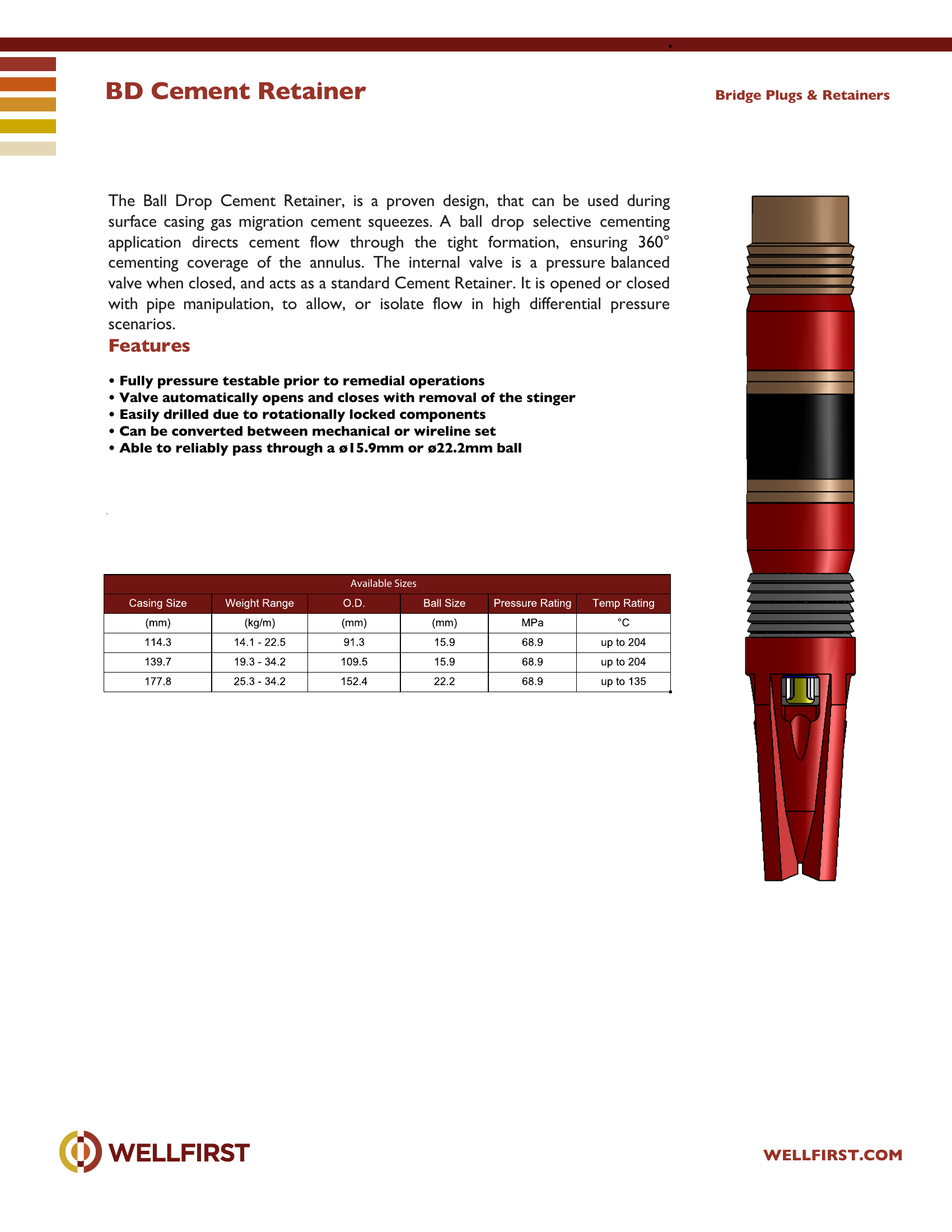
BD Cement Retainer The Ball Drop Cement Retainer, is a proven design, that can be used during surface casing gas migration cement squeezes. A ball drop selective cementing application directs cement flow through the tight formation, ensuring 360° cementing coverage of the annulus. The internal valve is a pressure balanced valve when closed, and acts as a standard Cement Retainer. It is opened or closed with pipe manipulation, to allow, or isolate flow in high differential pressure scenarios.

Key features
  • Fully pressure testable prior to remedial operations
  • Valve automatically opens and closes with removal of the stinger
  • Easily drilled due to rotationally locked components
  • Can be converted between mechanical or wireline set
  • Able to reliably pass through a ø15.9mm or ø22.2mm ball Bridge Plugs & Retainers Available Sizes

Complete dimensional data, part numbering and setting procedures are in the PDF.
Bridge Plugs|•| 
Full data sheet (PDF)
DB Bridge Plugs

DB Bridge Plugs

10,000 psi300 °F
PDF
DB Bridge Plugs

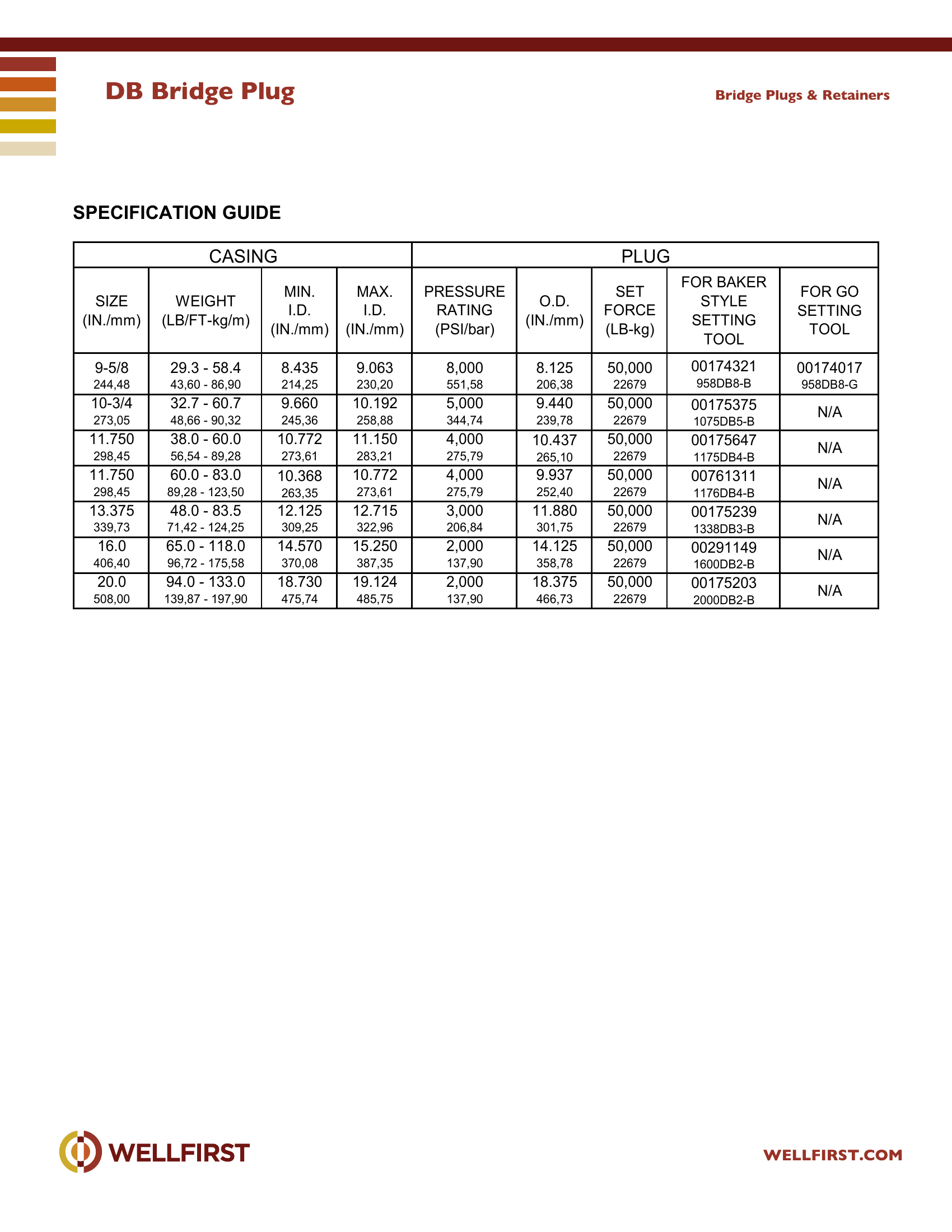
DB Bridge Plug The WELLFIRST Premium Cast Iron Bridge Plug designed to run on electric line. Rated between 2000 - 10000-psi differential, and 300°F from above and below.

Key features
  • Field Proven Design
  • Constructed of drillable materials
  • Top set with shear stud
  • Standard packing element rated at 300 °F
  • One piece slips Benefits
  • Rated to 2,000 psi to 10,000 psi differential from above and below at 300°F,
Data sheet ratingValue
Max pressure (data sheet)10,000 psi
Max temperature (data sheet)300 °F
Data sheet tables
SIZE (IN./mm)CASING WEIGHT (LB/FT - kg/m)MIN. I.D. (IN./mm)MAX. I.D. (IN./mm)PLUG PRESSUE RATING (PSI/bar)O.D. (IN./mm)SET FORCE (LB-kg)FOR BAKER STYLE SETTINGFOR GO SETTING TOOL
2-3/8 60,334.0 - 5.8 5,95 - 8,631.780 45,212.074 52,6810,000 689,481.750 44,45*9,00000175237 (238DB10-B)00175387 (238DB10-G)
2-7/8 73,036.4 - 6.5 9,52 - 9,672.340 59,442.525 64,1410,000 689,482.220 56,39*9,00000172073 (278DB10-B)00172092 (278DB10-G)
3-1/2 88,905.75 - 10.3 8,56 - 15,332.867 72,823.258 82,7510,000 689,482.750 69,85*9,00000172186 (350DB10-B)00172216 (350DB10-G)
4 101,605.6 - 14.0 8,33 - 20,833.340 84,843.732 94,7910,000 689,483.140 79,7620,00000172153 (400DB10-B)00146056 (400DB10-G)
4-1/2 114,309.5 - 15.1 14,14 - 22,473.826 97,184.090 103,8910,000 689,483.562 90,4733,00000175013 (450DB10-B)00175198 (450DB10-G)
5 127,0011.5 - 20.8 17,11 - 30,954.156 105,564.560 115,8210,000 689,483.937 100,0033,00000172546 (500DB10-B)00172583 (500DB10-G)
5-1/2 139,7013.0 - 23.0 19,34 - 34,224.670 118,625.044 128,1210,000 689,484.312 109,5233,00000174656 (550DB10-B)00174808 (550DB10-G)
5-3/4 146,0514.0 - 25.2 20,83 - 37,504.890 124,215.290 134,3710,000 689,484.700 119,3833,00000230063 (575DB10-B)N/A
6-5/8 168,2817.0 - 32.0 25,30 - 47,625.675 144,156.135 155,8310,000 689,485.375 136,5350,00000173190 (658DB10-B)N/A
717.0 - 35.0 25,30 - 52,086.004 152,506.538 166,0710,000 689,485.687 144,4550,00000173135 (700DB10-B)00173132 (700DB10-G)
177,80
7 177,8017.0 - 29.0 25,30 - 43,156.184 157,076.538 166,0710,000 689,485.900 149,8650,00000741114 (700DB10LW-B)N/A
7-5/8 193,6820.0 - 39.0 29,76 - 58,036.625 168,287.125 180,9810,000 689,486.312 160,3250,00000173586 (758DB10-B)00173362 (758DB10-G)
8-5/8 219,0824.0 - 49.0 35,71 - 72,917.511 190,788.097 205,6610,000 689,487.144 181,4650,00000173358 (858DB10-B)00173368 (858DB10-G)

Complete dimensional data, part numbering and setting procedures are in the PDF.
Bridge Plugs|•| 
Full data sheet (PDF)
HM 1 Bridge Plugs

HM 1 Bridge Plugs

300 °F
PDF
HM 1 Bridge Plugs

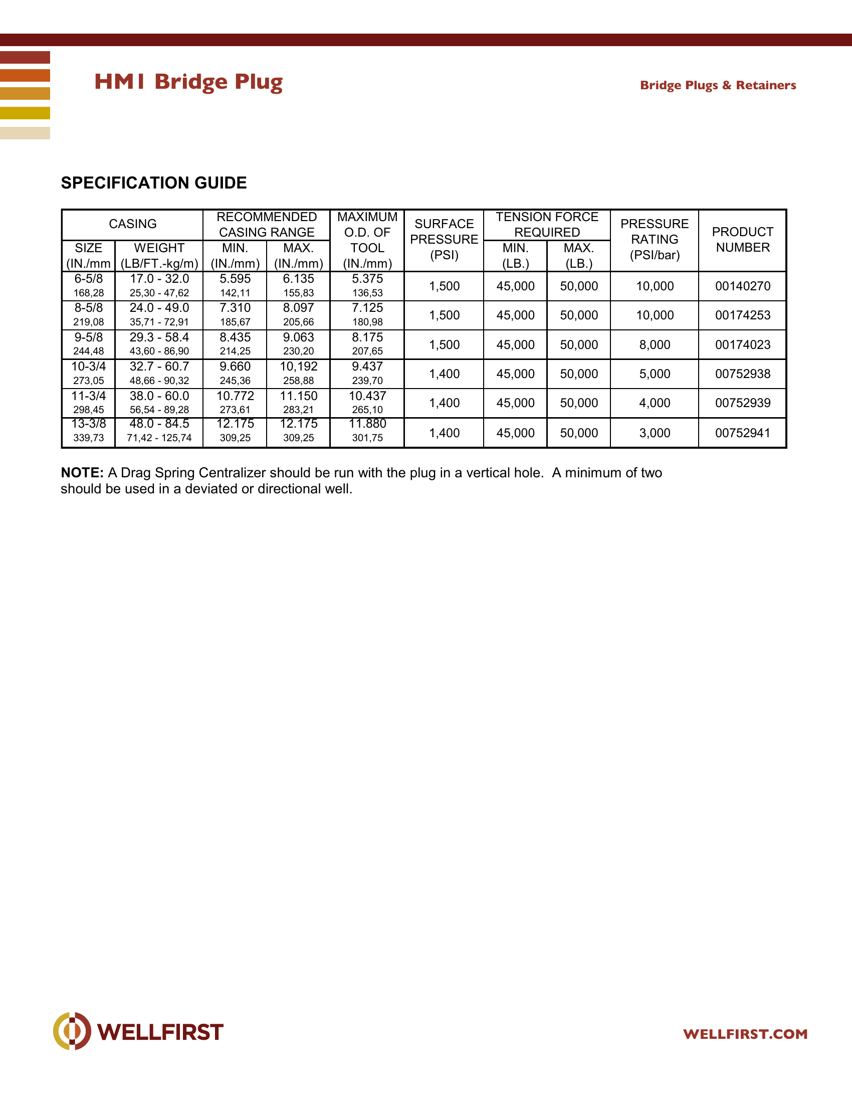
HM1 Bridge Plug The WELLFIRST HM-1 bridge plug is designed to set with a combination of hydraulic pressure and mechanical pull. The HM-1 bridge plug requires a setting tool.

Key features
  • Field Proven Design
  • Constructed of drillable materials
  • Right hand rotation releases setting tool from plug
  • Standard packing element rated at 300 °F
  • One piece slips Benefits
  • One setting tool sets plugs for 4 1/2 in. through 5 1/2 in. casing by changing
Data sheet ratingValue
Max temperature (data sheet)300 °F
Data sheet tables
CASING SIZE (IN./mmWEIGHT (LB/FT.-kg/m)RECOMMENDED CASING RANGEMAX. (IN./mm)AXIMUM O.D. OF TOOL IN./mm)SURFACE PRESSURE (PSI)TENSION FORCE REQUIREDMAX. (LB.)PRESSURE RATING (PSI/bar)PRODUCT NUMBER
6-5/8 168,2817.0 - 32.0 25,30 - 47,625.595 142,116.135 155,835.375 136,531,50045,00050,00010,00000140270
8-5/8 219,0824.0 - 49.0 35,71 - 72,917.310 185,678.097 205,667.125 180,981,50045,00050,00010,00000174253
9-5/8 244,4829.3 - 58.4 43,60 - 86,908.435 214,259.063 230,208.175 207,651,50045,00050,0008,00000174023
10-3/4 273,0532.7 - 60.7 48,66 - 90,329.660 245,3610,192 258,889.437 239,701,40045,00050,0005,00000752938
11-3/4 298,4538.0 - 60.0 56,54 - 89,2810.772 273,6111.150 283,2110.437 265,101,40045,00050,0004,00000752939
13-3/8 339,7348.0 - 84.5 71,42 - 125,7412.175 309,2512.175 309,2511.880 301,751,40045,00050,0003,00000752941

Complete dimensional data, part numbering and setting procedures are in the PDF.
Bridge Plugs|•| 
Full data sheet (PDF)
HM 2 Bridge Plugs

HM 2 Bridge Plugs

300 °F
PDF
HM 2 Bridge Plugs

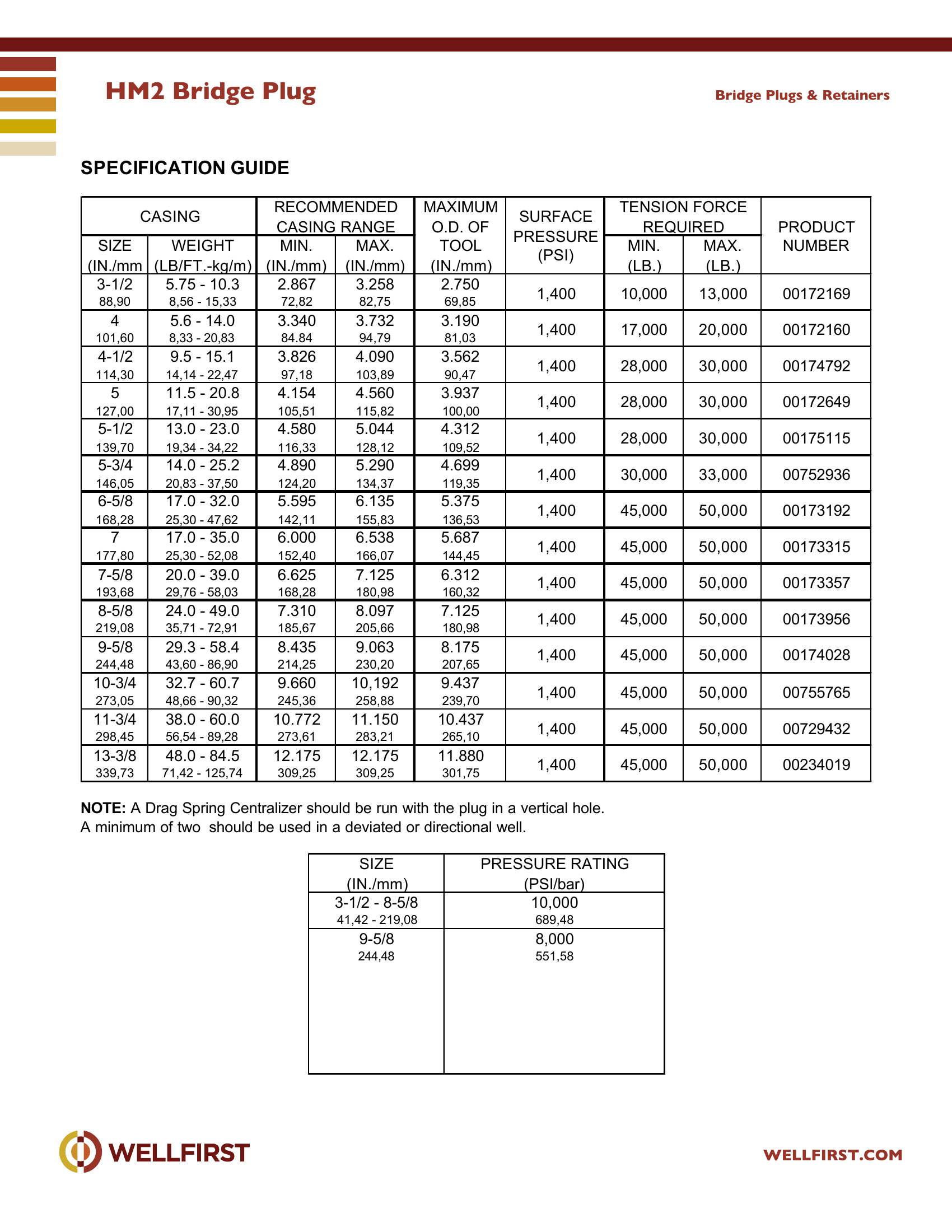
HM2 Bridge Plug The WELLFIRST HM-2 Permanent Cast Iron Bridge Plug is designed especially for use in high-pressure situations. The HM -2 bridge plug is designed to set with a combination of hydraulic pressure and mechanical pull and is designed with built in setting tool for greater efficiency.

Key features
  • Field Proven Design
  • Constructed of drillable materials
  • Right hand rotation releases setting tool from plug
  • Standard packing element rated at 300 °F
  • One piece slips Benefits
  • Built-in setting tool
Data sheet ratingValue
Max temperature (data sheet)300 °F
Data sheet tables
CASING SIZE (IN./mmWEIGHT (LB/FT.-kg/m)RECOMMENDED CASING RANGEMAX. (IN./mm)MAXIMUM O.D. OF TOOL (IN./mm)SURFACE PRESSURE (PSI)TENSION FORCE REQUIREDMAX. (LB.)PRODUCT NUMBER
3-1/2 88,905.75 - 10.3 8,56 - 15,332.867 72,823.258 82,752.750 69,851,40010,00013,00000172169
4 101,605.6 - 14.0 8,33 - 20,833.340 84.843.732 94,793.190 81,031,40017,00020,00000172160
4-1/2 114,309.5 - 15.1 14,14 - 22,473.826 97,184.090 103,893.562 90,471,40028,00030,00000174792
5 127,0011.5 - 20.8 17,11 - 30,954.154 105,514.560 115,823.937 100,001,40028,00030,00000172649
5-1/2 139,7013.0 - 23.0 19,34 - 34,224.580 116,335.044 128,124.312 109,521,40028,00030,00000175115
5-3/4 146,0514.0 - 25.2 20,83 - 37,504.890 124,205.290 134,374.699 119,351,40030,00033,00000752936
6-5/8 168,2817.0 - 32.0 25,30 - 47,625.595 142,116.135 155,835.375 136,531,40045,00050,00000173192
7 177,8017.0 - 35.0 25,30 - 52,086.000 152,406.538 166,075.687 144,451,40045,00050,00000173315
7-5/8 193,6820.0 - 39.0 29,76 - 58,036.625 168,287.125 180,986.312 160,321,40045,00050,00000173357
8-5/8 219,0824.0 - 49.0 35,71 - 72,917.310 185,678.097 205,667.125 180,981,40045,00050,00000173956
9-5/8 244,4829.3 - 58.4 43,60 - 86,908.435 214,259.063 230,208.175 207,651,40045,00050,00000174028
10-3/4 273,0532.7 - 60.7 48,66 - 90,329.660 245,3610,192 258,889.437 239,701,40045,00050,00000755765
11-3/4 298,4538.0 - 60.0 56,54 - 89,2810.772 273,6111.150 283,2110.437 265,101,40045,00050,00000729432
13-3/8 339,7348.0 - 84.5 71,42 - 125,7412.175 309,2512.175 309,2511.880 301,751,40045,00050,00000234019
SIZE (IN./mm)PRESSURE RATING (PSI/bar)
3-1/2 - 8-5/8 41,42 - 219,0810,000 689,48
9-5/8 244,488,000 551,58

Complete dimensional data, part numbering and setting procedures are in the PDF.
Bridge Plugs|•| 
Full data sheet (PDF)
High Flow Cement Retainer

High Flow Cement Retainer

PDF
High Flow Cement Retainer

High Flow Cement Retainer

Key features
  • Large flow area for fluid dumping as in a disposal, or large cement squeeze
  • The bypass ports are aligned for maximum fluid movement with minimum
  • When the valve is open, the seals are protected from fluid erosion.
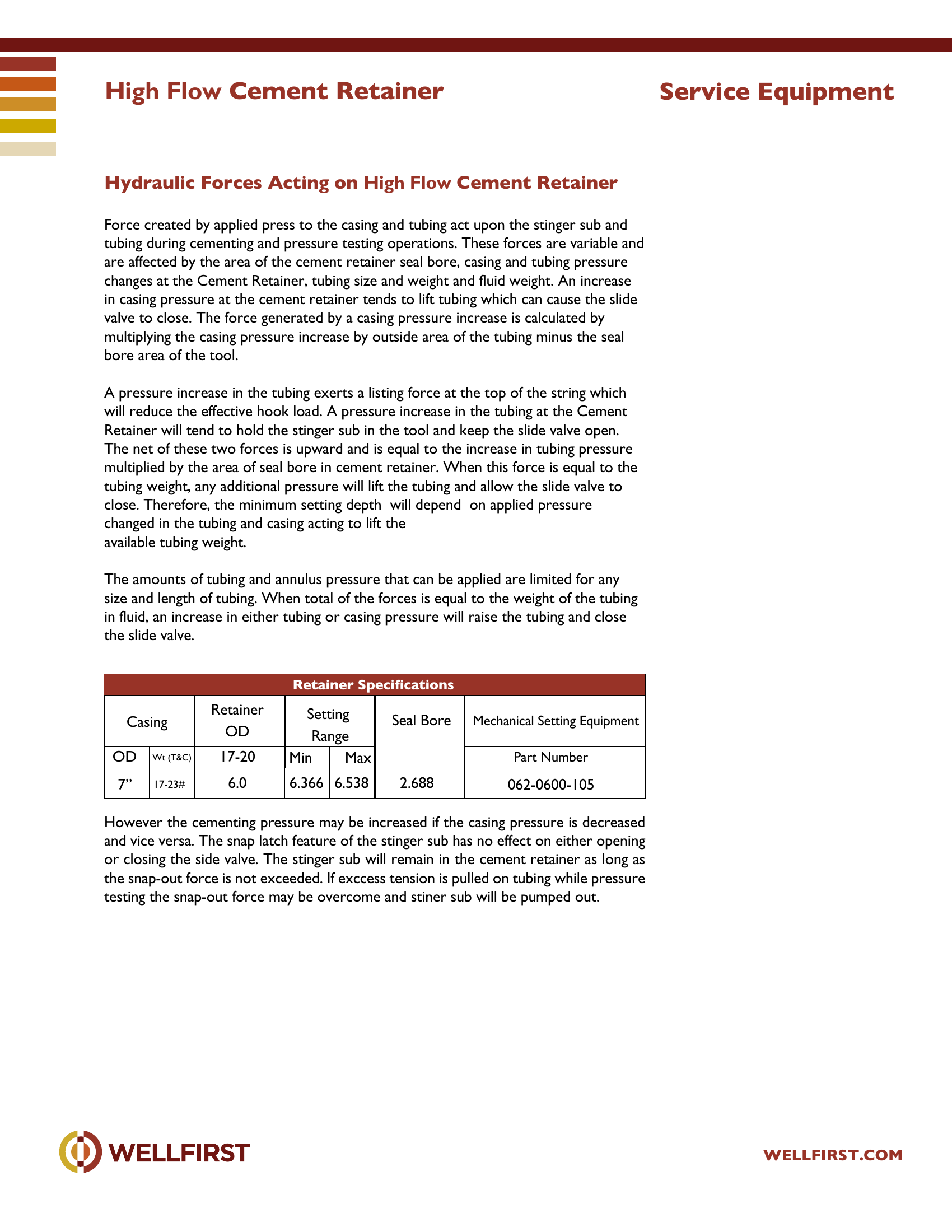
  • The valve sleeve is pressure balanced to prevent sudden opening from creep. features to prevent premature setting of the retainer or bridge plug or damage to the tool. It is suggested that the tool be run at a moderate speed while avoiding sudden stops. Note: While running in, care must be taken to prevent right-hand rotation from being transmitted to the setting tool. Under no circumstance must there be allowed more than four turns of the tubing to the right while running in. As a precaution, after every 10 to 15 stands, at least one or more left hand turns should be placed in the work string to assure the control nut is “bumped up”. When the desired setting depth has been reached, the tools should be picked up two (2) feet above the desired setting point. This movement is necessary to provide the required tool stroke to release the upper slips and allow the Control Nut to move freely. Rotate the work string to the right sufficiently to transmit 10 turns to the tool. This right-hand rotation will thread the Control Nut off its matching thread on the Mechanical Setting Tool mandrel and release the Control Sleeve from the running in position. Lower the tools back down to the desired setting depth. The Drag Blocks will support the Control Sleeve and Setting Sleeve. The downward motion will push the upper slips from under the Setting Sleeve. attached to the inside of each slip segment. When the upper slips are released, the Retaining Sleeve is pulled from over the Dog allowing it to move out and release the Control Latch from the Stinger Sub Body. Refer to the following chart and pull tension It is recommended that the maximum tension shown above be pulled when possible. must be pulled. Set down weight equal to the calculated weight required to prevent the slide valve from closing during pumping operations. Do not apply tension after setting weight on retainer other than that required to release setting tool or close valve. Pull a slight strain on work string and pressure the work string to insure that the slide valve is Contd... 7” Min. Tension Max. Tension High Flow Cement Retainer WELLFIRST.COM Service Equipment Operating Instructions, continued SPECIAL NOTE: In wells where paraffin or suspended solids in the well fluids are This is indicated when the Cement Retainer sets properly, as in steps 1 through 5, but the slide valve will not close so that the work string can be pressure tested. In this event the work string should be alternately picked up and slacked off. This movement will assist the Dog to move outward on the inclined edges of the locking groove in the Stinger Sub Body, thus freeing the Sub Body for the required two (2) inches of vertical The Mechanical Setting tool is released from the Cement Retainer by pulling 500-1000 lbs. tension at the tool and then rotating the work string 10 turns to the right at the tool. This will shear the rotational lock screw and unscrew the Control Latch from After Releasing from a Cement Retainer The Mechanical Setting Tool can be reattached to the Cement Retainer by setting down 3,000 to 5,000 lbs. of work string weight and snapped out again by pulling 8,000 to 10,000 lbs. tension at the Cement Retainer. The Stinger Seal will remain in the Cement Retainer until the snap-out retaining force is exceeded. Each time the Mechanical Setting Tool is snapped in and snapped out, the snap-in and snap-out value is reduced until they stabilize at about 2,500 pounds snap-in and 5,000 pounds snap-out. Two (2) inches of upward movement at the Cement Retainer will close the slide valve; two (2) inches of

Complete dimensional data, part numbering and setting procedures are in the PDF.
Bridge Plugs|•| 
Full data sheet (PDF)
Latch Style Cement Retainer

Latch Style Cement Retainer

PDF
Latch Style Cement Retainer

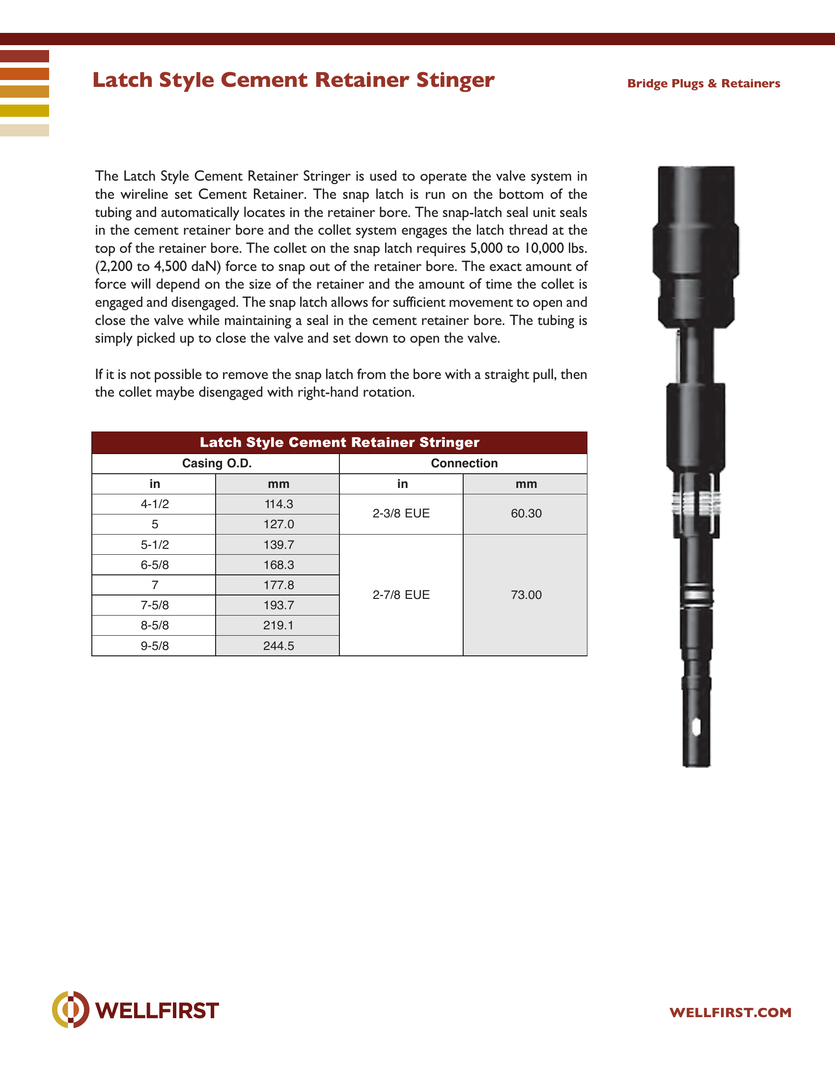
The Latch Style Cement Retainer Stringer is used to operate the valve system in the wireline set Cement Retainer. The snap latch is run on the bottom of the tubing and automatically locates in the retainer bore. The snap-latch seal unit seals in the cement retainer bore and the collet system engages the latch thread at the top of the retainer bore. The collet on the snap latch requires 5,000 to 10,000 lbs. (2,200 to 4,500 daN) force to snap out of the retainer bore. The exact amount of force will depend on the size of the retainer and the amount of time the collet is engaged and disengaged. The snap latch allows for sufficient movement to open and close the valve while maintaining a seal in the cement retainer bore. The tubing is simply picked up to close the valve and set down to open the valve. If it is not possible to remove the snap latch from the bore with a straight pull, then the collet maybe disengaged with right-hand rotation. Bridge Plugs & Retainers Casing O.D. Conn ection

Data sheet tables
Casing O.D. inmmConnection inmm
4-1/2114.32-3/8 EUE
60.30
5127.0
5-1/2139.72-7/8 EUE
6-5/8168.3
7177.8
73.00
7-5/8193.7
8-5/8219.1
9-5/8244.5

Complete dimensional data, part numbering and setting procedures are in the PDF.
Bridge Plugs|•| 
Full data sheet (PDF)
Mechanical Cement Retainer Tool

Mechanical Cement Retainer Tool

PDF
Mechanical Cement Retainer Tool

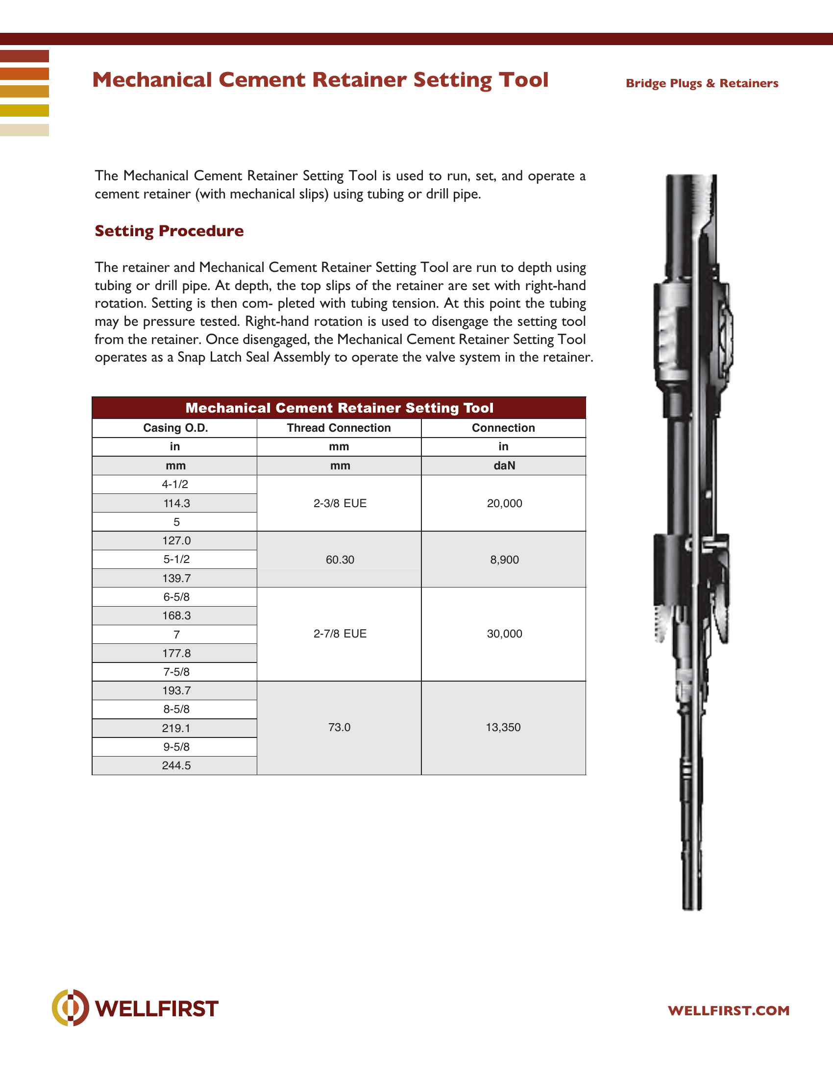
The Mechanical Cement Retainer Setting Tool is used to run, set, and operate a cement retainer (with mechanical slips) using tubing or drill pipe. Setting Procedure The retainer and Mechanical Cement Retainer Setting Tool are run to depth using tubing or drill pipe. At depth, the top slips of the retainer are set with right-hand rotation. Setting is then com- pleted with tubing tension. At this point the tubing may be pressure tested. Right-hand rotation is used to disengage the setting tool from the retainer. Once disengaged, the Mechanical Cement Retainer Setting Tool operates as a Snap Latch Seal Assembly to operate the valve system in the retainer. Bridge Plugs & Retainers Casing O.D. Thread Connection Connection in n i m m N a d m m m m

Data sheet tables
Casing O.D. in mmThread Connection mmConnection in daN
4-1/22-3/8 EUE20,000
114.3
5
127.060.308,900
5-1/2
139.7
6-5/82-7/8 EUE30,000
168.3
7
177.8
7-5/8
193.773.013,350
8-5/8
219.1
9-5/8
244.5

Complete dimensional data, part numbering and setting procedures are in the PDF.

Bridge Plugs|•| 
Full data sheet (PDF)
Mill-EZ Composite Bridge Plug

Mill-EZ Composite Bridge Plug

PDF
Mill-EZ Composite Bridge Plug

Mill-EZ Composite Bridge Plug The Mill-EZ Composite Bridge Plug is a slim design bridge plug. The Mill-EZ's low metallic content allows for the plug to be quickly and easily milled and circulated back to surface. The bottom is designed for milling of several plugs in the same wellbore. This can be accomplished with conventional milling with a rig or coiled tubing.

Key features
  • Can be set on wireline, coiled tubing, or production tubing
  • Utilizes conventional setting tools
  • Multiple plugs in a single wellbore
  • Mill or drill multiple plugs in a single run
  • Can be milled or drilled with coiled tubing
  • Utilizes conventional milling or drilling tools
Data sheet tables
Casing Bridge BridgeWeightLow Low HighHigh psi YellowHigh psi Blue
2.3754.71.75011.0250 /10K250 /10K350 /10KGO
2.8756.52.20011.0250 /10K250 /10K350 /10KBaker #5 or GO
2-7/8 HW7.92.15011.0250 /10K250 /10K350 /10KBaker #5 or GO
3-1/29.30 - 10.202.72511.0250 /10K250 /10K350 /10KBaker #5 or GO
3-1/2 HW12.952.50011.0250 /10K250 /10K350 /10KBaker #5 or GO
49.50 - 11.03.18816.0250 /10K250 /10K350 /10KBaker #10 or GO
4-1/29.50 - 11.03.60016.0250 /10K250 /10K350 /10KBaker #10 or GO
511.5 - 203.92016.0250 /10K250 /10K350 /10KBaker #10 or GO
5-1/215.5 - 234.40016.0250 /10K250 /10K350 /10KBaker #20 or GO
720 - 355.75018.0250 /10K250 /10K350 /10KBaker #20 or GO
7-5/824 - 33.76.40018.0350 /10KBaker #20 or GO
8-5/836 - 497.25022.0250 /10KBaker #20 or GO
9-5/832.3 - 53.58.37522.0250 /10KBaker #20 or GO

Complete dimensional data, part numbering and setting procedures are in the PDF.
Bridge Plugs|•| 
Full data sheet (PDF)
WRN Retrieving Tool

WRN Retrieving Tool

PDF
WRN Retrieving Tool

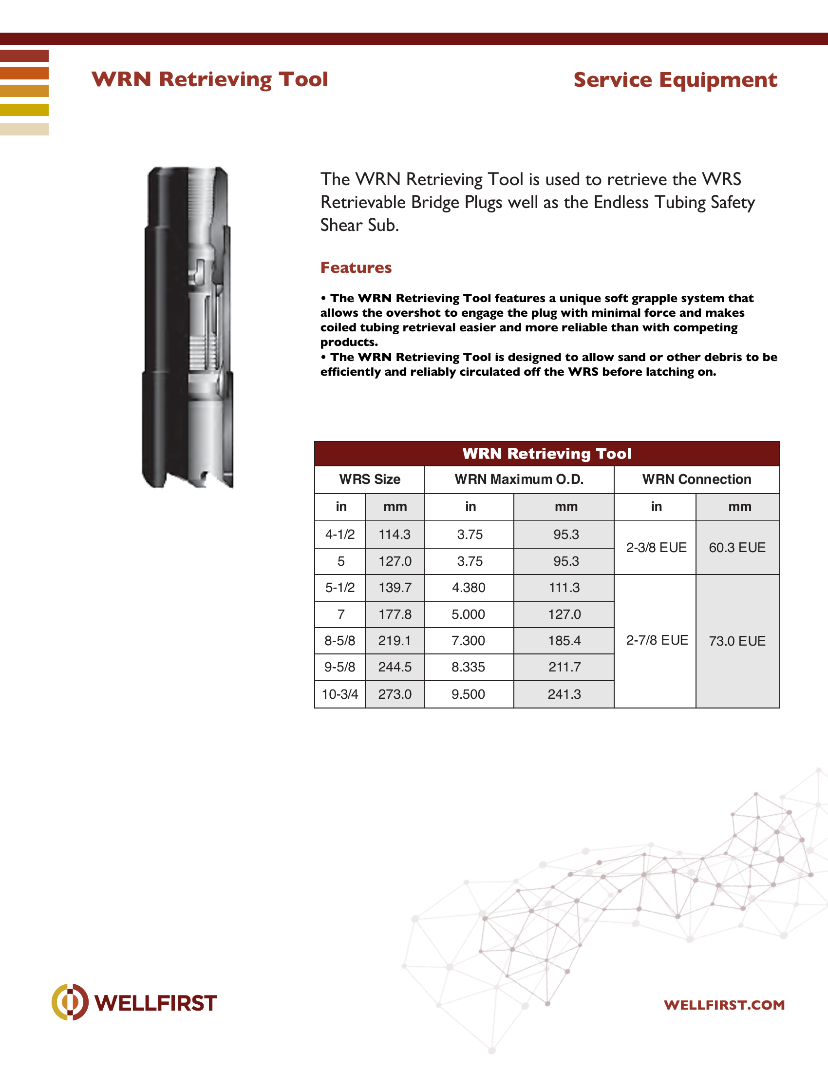
WRN Retrieving Tool The WRN Retrieving Tool is used to retrieve the WRS Retrievable Bridge Plugs well as the Endless Tubing Safety Shear Sub.

Key features
  • The WRN Retrieving Tool features a unique soft grapple system that allows the overshot to engage the plug with minimal force and makes coiled tubing retrieval easier and more reliable than with competing
  • The WRN Retrieving Tool is designed to allow sand or other debris to be Service Equipment WRS Size WRN Maximum O.D. WRN C onnec tion in mm in mm in mm 4-1/2 114.3 3.75 95.3 2-3/8 EUE 60.3 EUE 5 127.0 3.75 95.3 5-1/2 139.7 4.380 111.3 2-7/8 EUE 73.0 EUE 7 177.8 5.000 127.0 8-5/8 219.1 7.300 185.4 9-5/8 244.5 8.335 211.7 10-3/4 273.0 9.500 241.3
Data sheet tables
WRS Size inmmWRN Maximum O.D. inmmWRN Connection inmm
4-1/2114.33.7595.32-3/8 EUE
60.3 EUE
5127.03.7595.3
5-1/2139.74.380111.32-7/8 EUE
7177.85.000127.0
8-5/8219.17.300185.4
73.0 EUE
9-5/8244.58.335211.7
10-3/4273.09.500241.3

Complete dimensional data, part numbering and setting procedures are in the PDF.
Bridge Plugs|•| 
Full data sheet (PDF)
WRS Retrievable Plug

WRS Retrievable Plug

PDF
WRS Retrievable Plug

WRS Retrievable Bridge Plug The WRS Bridge Plug is a wireline set, retrievable bridge plug used for zone isolation, surface equipment repair, or any other application in which a reliable retrievable bridge plug is required. The WRS Bridge Plug is commonly run on wireline using an E4 pressure setting tool (or equivalent). However, it may be set on conventional or coiled tubing using a hydraulic setting tool. The plug may be retrieved on conventional or coiled tubing using the WRN Retrieving Tool.

Key features
  • Safe releasing — when releasing, the WRN Retrieving Tool automatically
  • Short, compact design allows setting in applications where the setting
  • When using a special adapter, recorders may be run below the plug. The system allows recorders to be run inside a tube below the plug to prevent damage to the
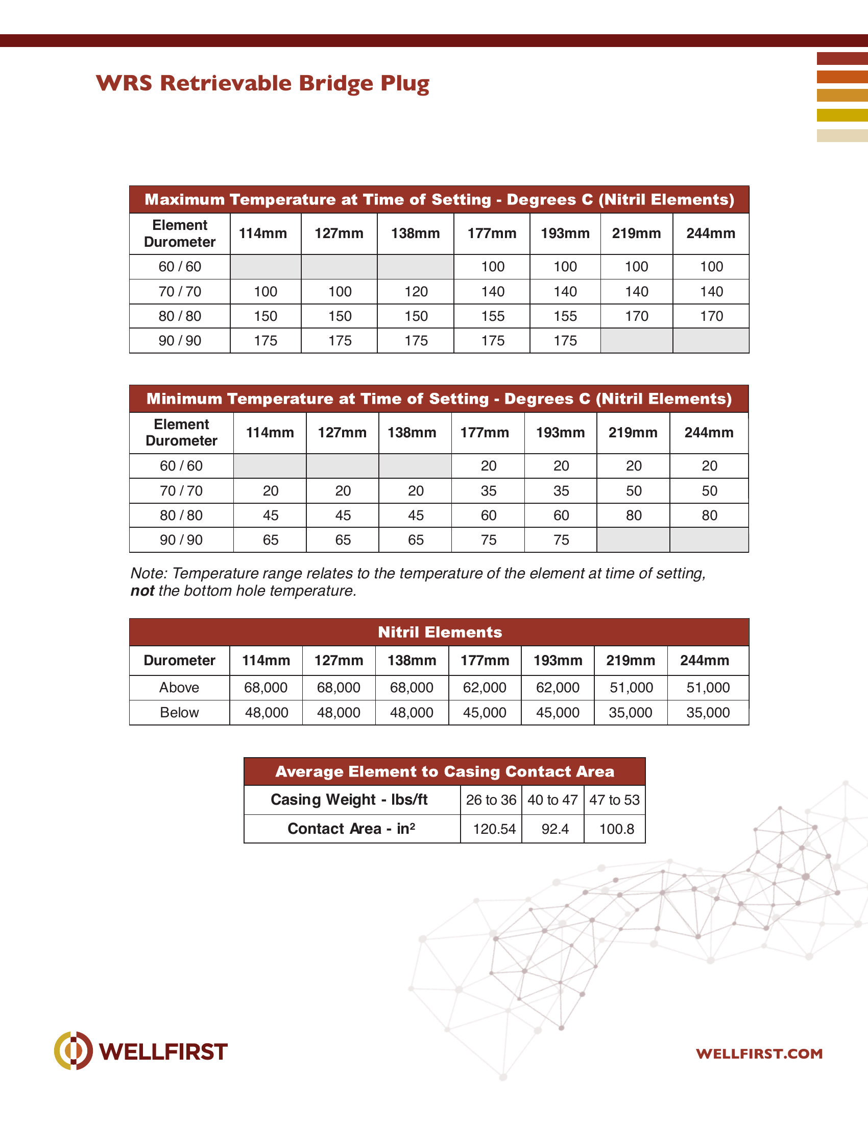
  • The WRS may be lubricated into wells under pressure on wireline or on Service Equipment Casing WRS O.D.O.D. Weight Range in mm lb/ft kg/m in mm in mm 4-1/2 114.3 9.5 - 13.5 14.1 - 20.1 4.090 - 3.920 103.9 - 99.6 3.750 95.25 5 127.0 1 1.5 - 13 17.1 - 19.3 4.560 - 4.494 115.8 - 1 14.1 4.220 107.19 15 - 18 22.3 - 26.7 4.408 - 4.276 111.9 - 108.6 4.100 104.14 5-1/2 139.7 13 - 17 19.3 - 25.3 5.044 - 4.892 128.2 - 124.2 4.620 117.35 17 - 23 25.3 - 34.2 4.892 - 4.670 124.2 - 1 18.6 4.500 114.30 7 177.8 17 - 20 25.3 - 29.8 6.538 - 6.456 166.1 - 164.0 6.250 158.75 23 - 26 34.2 - 38.7 6.366 - 6.276 161.7 - 159.4 6.050 153.67 26 - 32 38.7 - 47.6 6.276 - 6.094 159.4 - 154.8 5.875 149.22 8-5/8 219.1 20 - 28 24.8 - 41.7 8.017 - 8.191 203.6 - 208.1 7.531 197.6 32 - 40 47.6 - 59.5 7.725 - 7.921 196.2 - 201.2 7.312 191.3 44 - 49 65.5 - 72.9 7.511 - 7.625 190.8 - 193.7 7.281 185.7 9-5/8 244.5 29.3 - 36 43.6 - 53.6 8.921 - 9.063 226.6 - 230.2 8.593 218.3 40 - 47 59.5 - 69.9 8.681 - 8.835 220.5 - 224.4 8.437 214.3 47 - 53.5 69.9 - 79.6 8.535 - 8.681 216.8 - 220.5 8.218 208.7 10-3/4 273.0 45.5 - 51 67.7 - 75.9 9.950 - 9.850 252.7 - 250.1 9.500 241.3 32.75 - 40.5 48.7 - 60.3 10.192 - 10 .050 258.8 - 255.2 9.700 246.4 Other sizes and weight ranges available upon request. 60 / 60 100 100 100 100 70 / 70 100 100 120 140 140 140 140 80 / 80 150 150 150 155 155 170 170 90 / 90 175 175 175 175 175 Element Durometer 114mm 127mm 138mm 177mm 193mm 219mm 244mm 60 / 60 20 20 20 20 70 / 70 20 20 20 35 35 50 50 80 / 80 45 45 45 60 60 80 80 90 / 90 65 65 65 75 75 Note: Temperature range relates to the temperature of the element at time of setting, Durometer 114mm 127mm 138mm 177mm 193mm 219mm 244mm Above 68,000 68,000 68,000 62,000 62,000 51,000 51,000 Below 48,000 48,000 48,000 45,000 45,000 35,000 35,000 Casing Weight - lbs/ft 26 to 36 40 t o 47 47 t o 53 Contact Area - in2 120.54 92.4 100.8
Data sheet tables
Casing O.D. inmmWeight lb/ftkg/mRange inmmWRS O.D. inmm
4-1/2114.39.5 - 13.514.1 - 20.14.090 - 3.920103.9 - 99.63.75095.25
511.5 - 1317.1 - 19.34.560 - 4.494115.8 - 114.14.220107.19
127.0
15 - 1822.3 - 26.74.408 - 4.276111.9 - 108.64.100104.14
5-1/213 - 1719.3 - 25.35.044 - 4.892128.2 - 124.24.620117.35
139.7
17 - 2325.3 - 34.24.892 - 4.670124.2 - 118.64.500114.30
717 - 2025.3 - 29.86.538 - 6.456166.1 - 164.06.250158.75
177.823 - 2634.2 - 38.76.366 - 6.276161.7 - 159.46.050153.67
26 - 3238.7 - 47.66.276 - 6.094159.4 - 154.85.875149.22
8-5/820 - 2824.8 - 41.78.017 - 8.191203.6 - 208.17.531197.6
219.132 - 4047.6 - 59.57.725 - 7.921196.2 - 201.27.312191.3
44 - 4965.5 - 72.97.511 - 7.625190.8 - 193.77.281185.7
9-5/829.3 - 3643.6 - 53.68.921 - 9.063226.6 - 230.28.593218.3
244.540 - 4759.5 - 69.98.681 - 8.835220.5 - 224.48.437214.3
47 - 53.569.9 - 79.68.535 - 8.681216.8 - 220.58.218208.7
10-3/445.5 - 5167.7 - 75.99.950 - 9.850252.7 - 250.19.500241.3
273.0
32.75 - 40.548.7 - 60.310.192 - 10.050258.8 - 255.29.700246.4
Element Duromete114mm r127mm138mm177mm193mm 219
60 / 60100100 10
70 / 70100100120140140 14
80 / 80150150150155155 17
90 / 90175175175175175
Element Duromet114mm er127mm138mm 177mm193mm 219
60 / 602020 2
70 / 702020203535 5
80 / 804545456060 8
90 / 906565657575

Complete dimensional data, part numbering and setting procedures are in the PDF.
Bridge Plugs|•| 
Full data sheet (PDF)
Wellfirst Cement Retainer

Wellfirst Cement Retainer

400 °F
PDF
Wellfirst Cement Retainer

WellFirst Cement Retainer

Key features
  • Cast Iron drillable design
  • Converts between mechanical and wireline set by changing top slips.
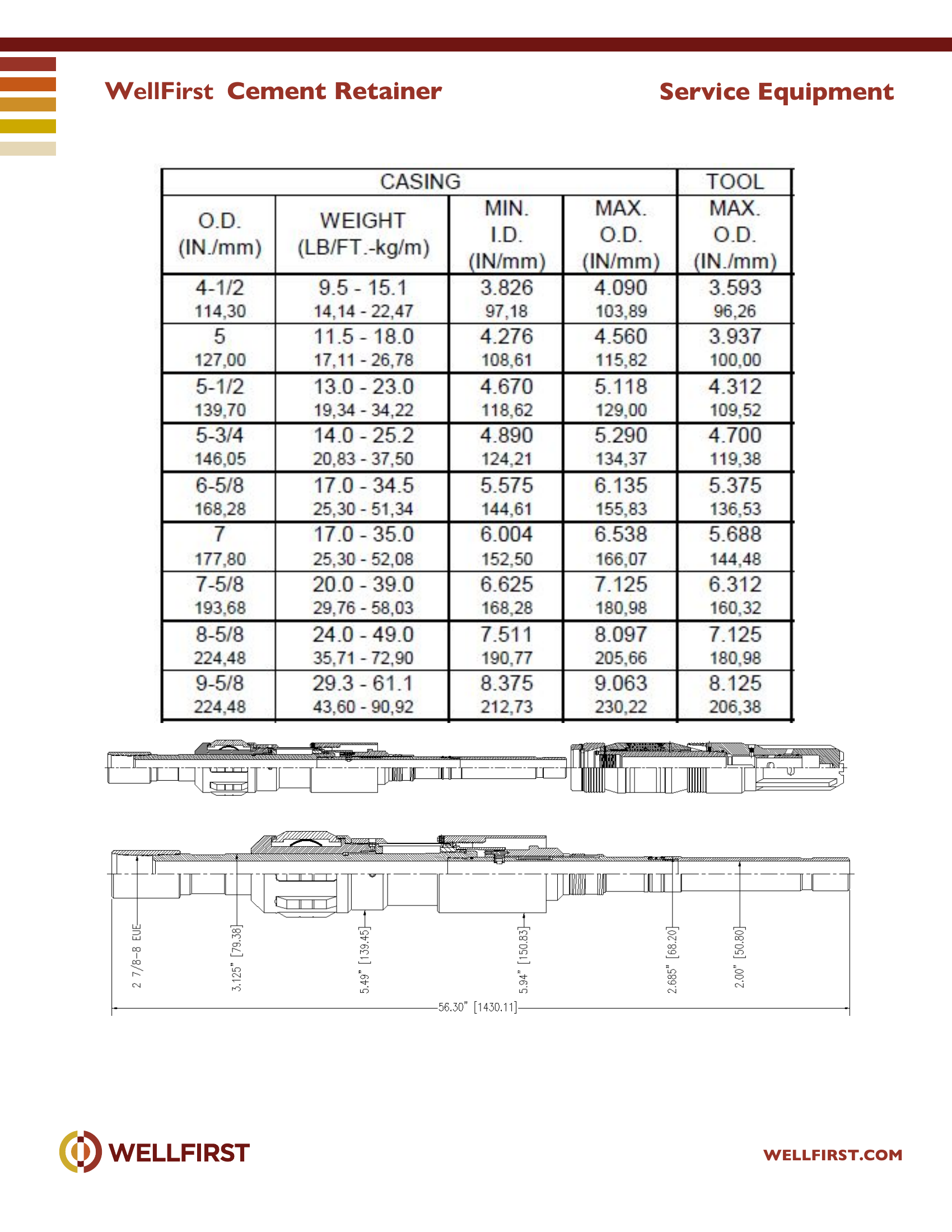
  • Simple, surface-controlled valve automatically closes when stinger is removed. features to prevent premature setting of the retainer or bridge plug or damage to the tool. It is suggested that the tool be run at a moderate speed while avoiding sudden stops. Note: While running in, care must be taken to prevent right-hand rotation from being transmitted to the setting tool. Under no circumstance must there be allowed more than four turns of the tubing to the right while running in. As a precaution, after every 10 to 15 stan ds, at least one or more left hand turns should be placed in the work string to assure the control nut is “bumped up”. When the desired setting depth has been reached, the tools should be picked up two (2) feet above the desired setting point. This movement is necessary to provide the required tool stroke to release the upper slips and allow the Control Nut to move freely. Rotate the work string to the right sufficiently to transmit 10 turns to the tool. This right-hand rotation will thread the Control Nut off its matching thread on the Mechanical Setting Tool mandrel and release the Control Sleeve from the running in position. Lower the tools back down to the desired setting depth. The Drag Blocks will support the Control Sleeve and Setting Sleeve. The downward motion will push the upper slips from under the Setting Sleeve. attached to the inside of each slip segment. When the upper slips are released, the Retaining Sleeve is pulled from over the Dog allowing it to move out and release the Control Latch from the Stinger Sub Body.
  • Temperature rating to 400F Benefits Allows pressure testing before squeeze• Valve protects sensitive zones in low-fluid wells• Fast drill out time saves rig time• WellFirst Cement Retainer WELLFIRST.COM Service Equipment
Data sheet ratingValue
Max temperature (data sheet)400 °F

Complete dimensional data, part numbering and setting procedures are in the PDF.

Bridge Plugs|•| 
Full data sheet (PDF)