
Wellfirst

WELLFIRST | a greater focus

PRODUCTS & SERVICES

Casing Patches

Wellfirst casing patch systems let operators repair damaged or corroded casing — or accommodate changed wellhead configurations — without pulling the string. The mechanical patch establishes a pressure-tight seal at the repair interval.

Applications

Repairs of cut-off casing stubs, corroded intervals and liner-top areas; casing-alternative projects.

Cost framing

A patch is a faster, lower-cost alternative to a full casing pull or workover.

Technical depth

Interval lengths and pressure retention data ship in each product PDF.

Casing Patches — 7 products

Gas Vent Pumping Packer

Gas Vent Pumping Packer

PDF
Gas Vent Pumping Packer

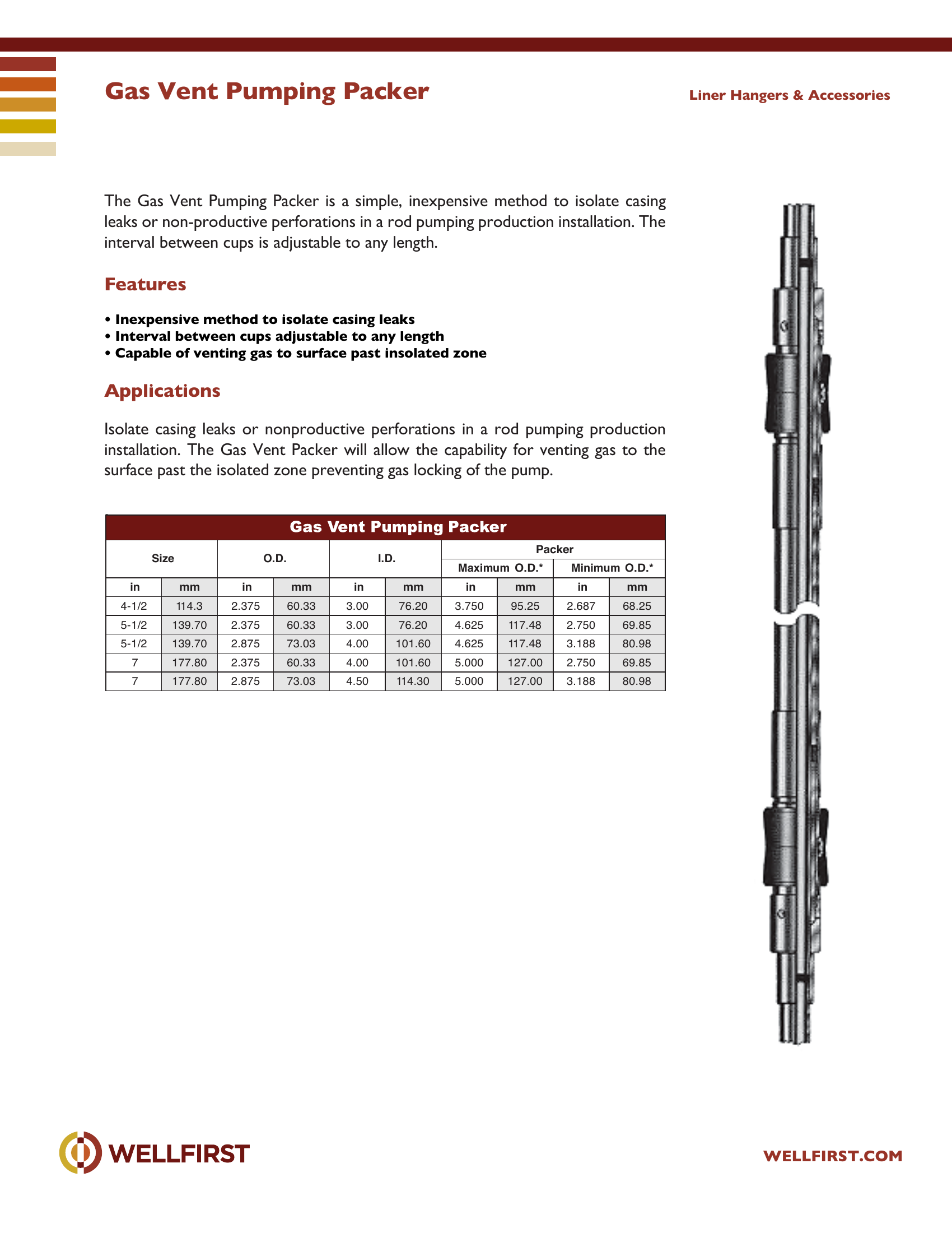
Gas Vent Pumping Packer The Gas Vent Pumping Packer is a simple, inexpensive method to isolate casing leaks or non-productive perforations in a rod pumping production installation. The interval between cups is adjustable to any length.

Key features
  • Inexpensive method to isolate casing leaks
  • Interval between cups adjustable to any length
  • Capable of venting gas to surface past insolated zone Applications Isolate casing leaks or nonproductive perforations in a rod pumping production installation. The Gas Vent Packer will allow the capability for venting gas to the Liner Hangers & Accessories Size O.D. I.D. in mm in mm in mm in mm in mm 4-1/2 114.3 2.375 60.33 3.00 76.20 3.750 95.25 2.687 68.25 5-1/2 139.70 2.375 60.33 3.00 76.20 4.625 117.48 2.750 69.85 5-1/2 139.70 2.875 73.03 4.00 101.60 4.625 117.48 3.188 80.98 7 177.80 2.375 60.33 4.00 101.60 5.000 127.00 2.750 69.85 7 177.80 2.875 73.03 4.50 114.30 5.000 127.00 3.188 80.98
Data sheet tables
Packer Size O.D.mminmminmmMaximum O.D.* inmmMinimum O.D.* inmm
4-1/2114.32.37560.333.0076.203.75095.252.68768.25
5-1/2139.702.37560.333.0076.204.625117.482.75069.85
5-1/2139.702.87573.034.00101.604.625117.483.18880.98
7177.802.37560.334.00101.605.000127.002.75069.85
7177.802.87573.034.50114.305.000127.003.18880.98

Complete dimensional data, part numbering and setting procedures are in the PDF.
Casing Patches|•| 
Full data sheet (PDF)
Model P Casing Patch

Model P Casing Patch

81,000 psi
PDF
Model P Casing Patch

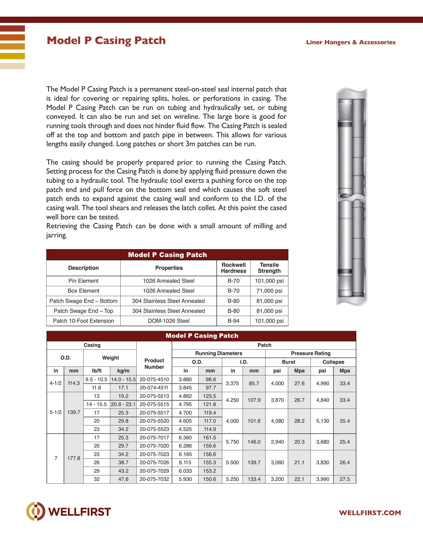
The Model P Casing Patch is a permanent steel-on-steel seal internal patch that is ideal for covering or repairing splits, holes, or perforations in casing. The Model P Casing Patch can be run on tubing and hydraulically set, or tubing conveyed. It can also be run and set on wireline. The large bore is good for running tools through and does not hinder fluid flow. The Casing Patch is sealed off at the top and bottom and patch pipe in between. This allows for various lengths easily changed. Long patches or short 3m patches can be run. The casing should be properly prepared prior to running the Casing Patch. Setting process for the Casing Patch is done by applying fluid pressure down the tubing to a hydraulic tool. The hydraulic tool exerts a pushing force on the top patch end and pull force on the bottom seal end which causes the soft steel patch ends to expand against the casing wall and conform to the I.D. of the casing wall. The tool shears and releases the latch collet. At this point the cased well bore can be tested. Retrieving the Casing Patch can be done with a small amount of milling and jarring. Liner Hangers & Accessories Description Prop erties Rockwell Ha rdness Te nsile Strength Pin Element 1026 A nnealed Steel B-70 101,00 0 psi Box Element 1026 A nnealed Steel B-70 71,000 psi Patch Swage End – Bottom 304 S tainless Steel Annealed B-80 81,000 psi Patch Swage End – Top 304 S tainless Steel Annealed B-80 81,000 psi Patch 10-Foot Extension DOM-102 6 Steel B-94 101,00 0 psi

Data sheet ratingValue
Max pressure (data sheet)81,000 psi
Data sheet tables
Casing O.D.WeightProduct NumberPatch Running Diameters O.D.I.D.Pressure Rating BurstCollapse
inmmlb/ftkg/minmminmmpsiMpapsiMpa
4-1/29.5 - 10.514.0 - 15.520-075-45103.88098.63.3754,0004,990
114.385.727.633.4
11.617.120-074-45113.84597.7
5-1/21319.220-075-55134.862123.54.2503,8704,840
14 - 15.520.8 - 23.120-075-55154.795121.8107.926.733.4
139.71725.320-075-55174.700119.44.0004,0805,130
2029.820-075-55204.605117.0101.628.235.4
2334.220-075-55234.525114.9
71725.320-075-70176.360161.55.7502,9403,680
2029.720-075-70206.286159.6146.020.325.4
2334.220-075-70236.165156.65.5003,0603,830
177.82638.720-075-70266.115155.3139.721.126.4
2943.220-075-70296.033153.2
3247.620-075-70325.930150.65.250133.43,20022.13,99027.5
Description Pin ElementProperties 1026 Annealed SteelRockwell Hardness B-70Tensile Strength 101,000
Patch Swage End – Bottom304 Stainless Steel AnnealedB-8081,000 psi
Patch Swage End – Top304 Stainless Steel AnnealedB-8081,000 psi
Patch 10-Foot ExtensionDOM-1026 SteelB-94101,000 psi

Complete dimensional data, part numbering and setting procedures are in the PDF.
Casing Patches|•| 
Full data sheet (PDF)
One-Trip Liner Running Assembly Tool

One-Trip Liner Running Assembly Tool

PDF
One-Trip Liner Running Assembly Tool

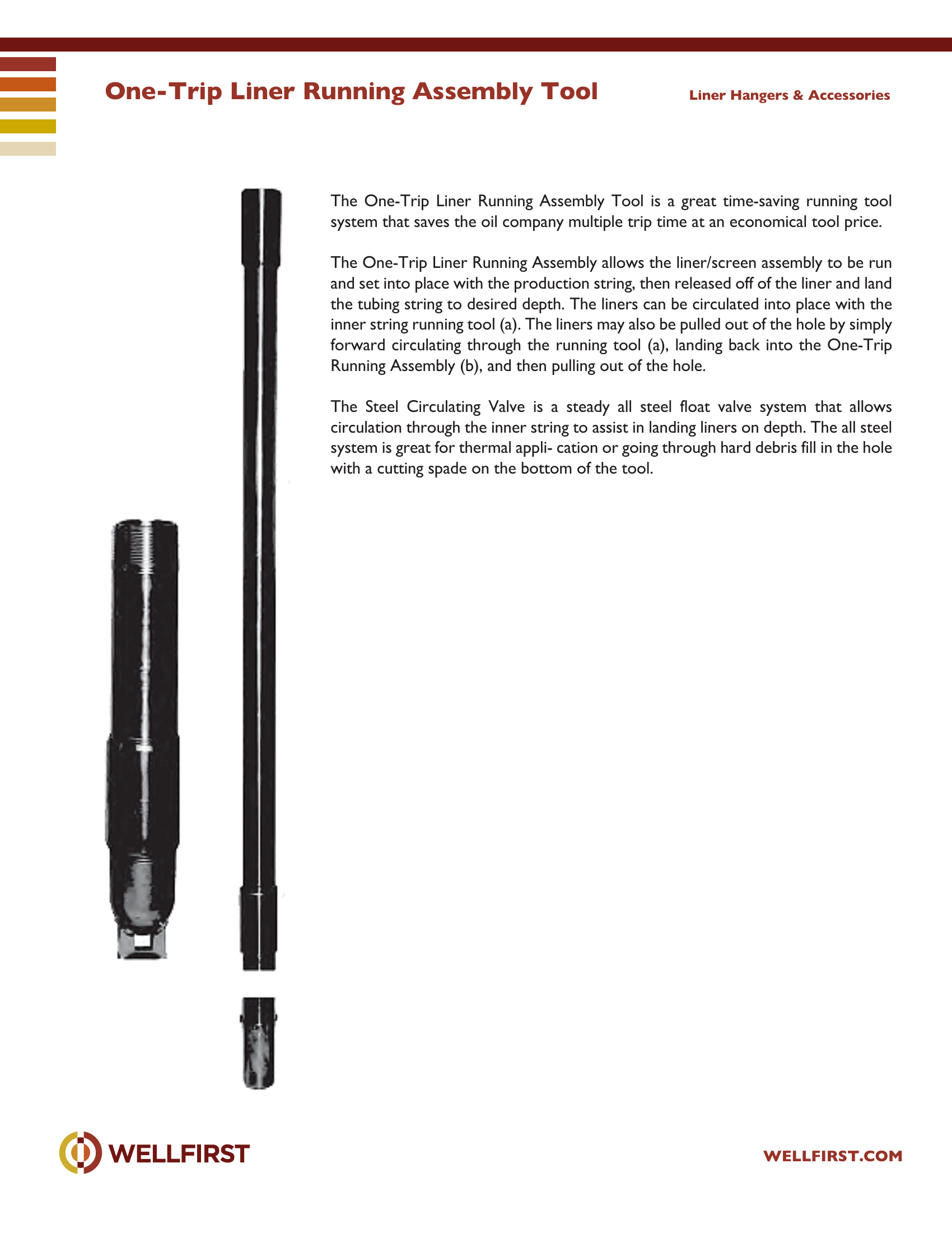
The One-Trip Liner Running Assembly Tool is a great time-saving running tool system that saves the oil company multiple trip time at an economical tool price. The One-Trip Liner Running Assembly allows the liner/screen assembly to be run and set into place with the production string, then released off of the liner and land the tubing string to desired depth. The liners can be circulated into place with the inner string running tool (a). The liners may also be pulled out of the hole by simply forward circulating through the running tool (a), landing back into the One-Trip Running Assembly (b), and then pulling out of the hole. The Steel Circulating Valve is a steady all steel float valve system that allows circulation through the inner string to assist in landing liners on depth. The all steel system is great for thermal appli- cation or going through hard debris fill in the hole with a cutting spade on the bottom of the tool. Liner Hangers & Accessories

Complete dimensional data, part numbering and setting procedures are in the PDF.
Casing Patches|•| 
Full data sheet (PDF)
Sure Seal Retrievable Casing Patch

Sure Seal Retrievable Casing Patch

PDF
Sure Seal Retrievable Casing Patch

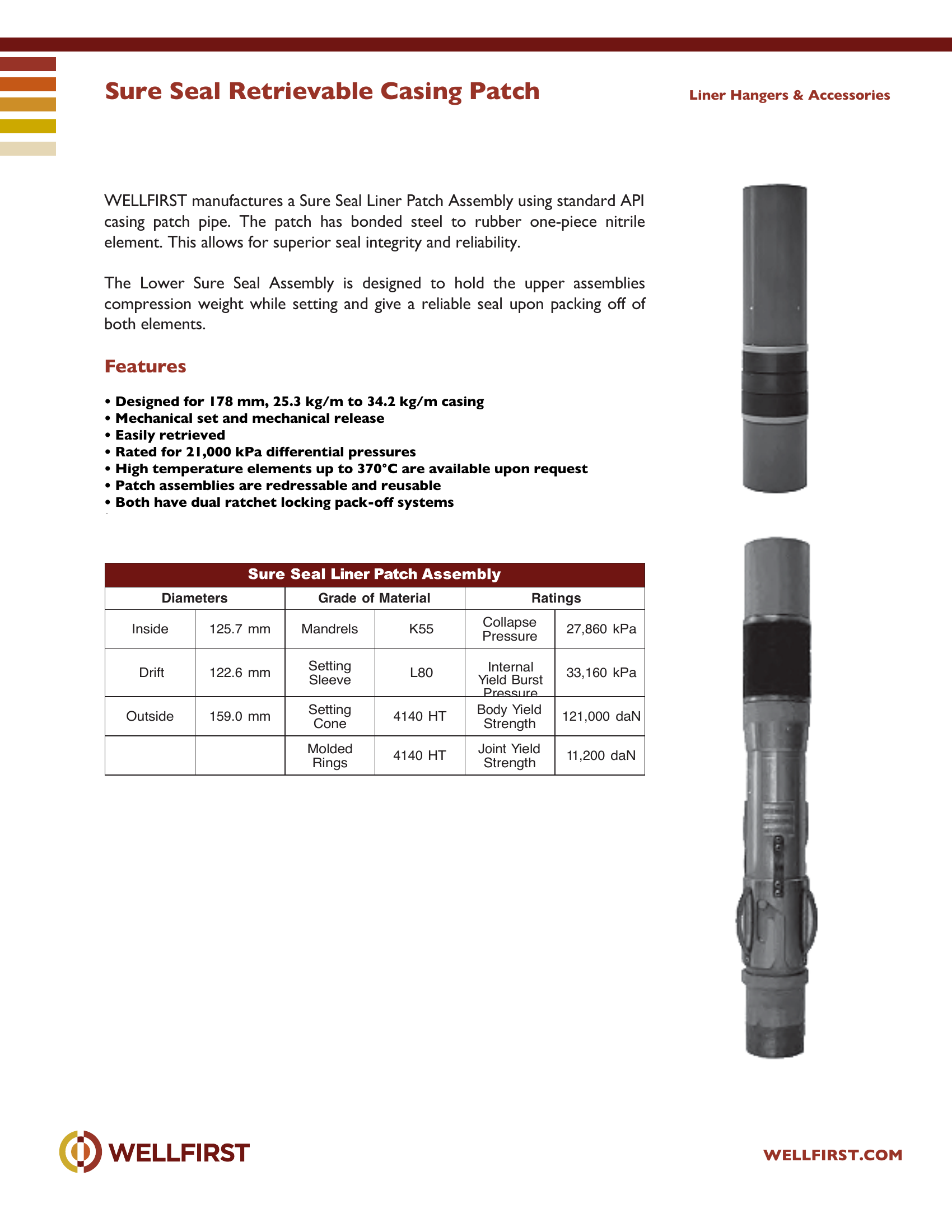
Sure Seal Retrievable Casing Patch WELLFIRST manufactures a Sure Seal Liner Patch Assembly using standard API casing patch pipe. The patch has bonded steel to rubber one-piece nitrile element. This allows for superior seal integrity and reliability. The Lower Sure Seal Assembly is designed to hold the upper assemblies compression weight while setting and give a reliable seal upon packing off of both elements.

Key features
  • Designed for 178 mm, 25.3 kg/m to 34.2 kg/m casing
  • Mechanical set and mechanical release
  • Easily retrieved
  • Rated for 21,000 kPa differential pressures
  • High temperature elements up to 370°C are available upon requ est
  • Patch assemblies are redressable and reusable
Data sheet tables
Diameters Inside Drift125.7 mm 122.6 mmGrade of MaterialK55 L80Ratings Collapse Pressure27,860 kPa 33,160 kPa
Outside159.0 mmSetting Cone4140 HTPressure Body Yield Strength121,000 daN
Molded Rings4140 HTJoint Yield Strength11,200 daN

Complete dimensional data, part numbering and setting procedures are in the PDF.
Casing Patches|•| 
Full data sheet (PDF)
Sure Seal Thermal Liner Hanger Patch

Sure Seal Thermal Liner Hanger Patch

PDF
Sure Seal Thermal Liner Hanger Patch

Sure Seal Thermal Liner Hanger Patch The Sure Seal Thermal Liner Hanger Patch is a mid-range hanger system capable of carrying 15,000 kg liner weight. It is economical and fast to operate with maximum fluid by-pass. The patch system uses standard casing or tubing for spacer pipe between ends and can be run with or without top hold-downs and slips. The SS Thermal Liner Hanger can be used in conjunction with the Thermal Sure Seal Thermal Adapter as an economical isolation tool for a casing patch.

Key features
  • One-piece mandrel with ratchet under cone
  • Open J
  • Large clearance for sand and debris
  • High temp thermal pack-off element
  • Can be run with inner circulating string
  • Extremely economical to service
Data sheet tables
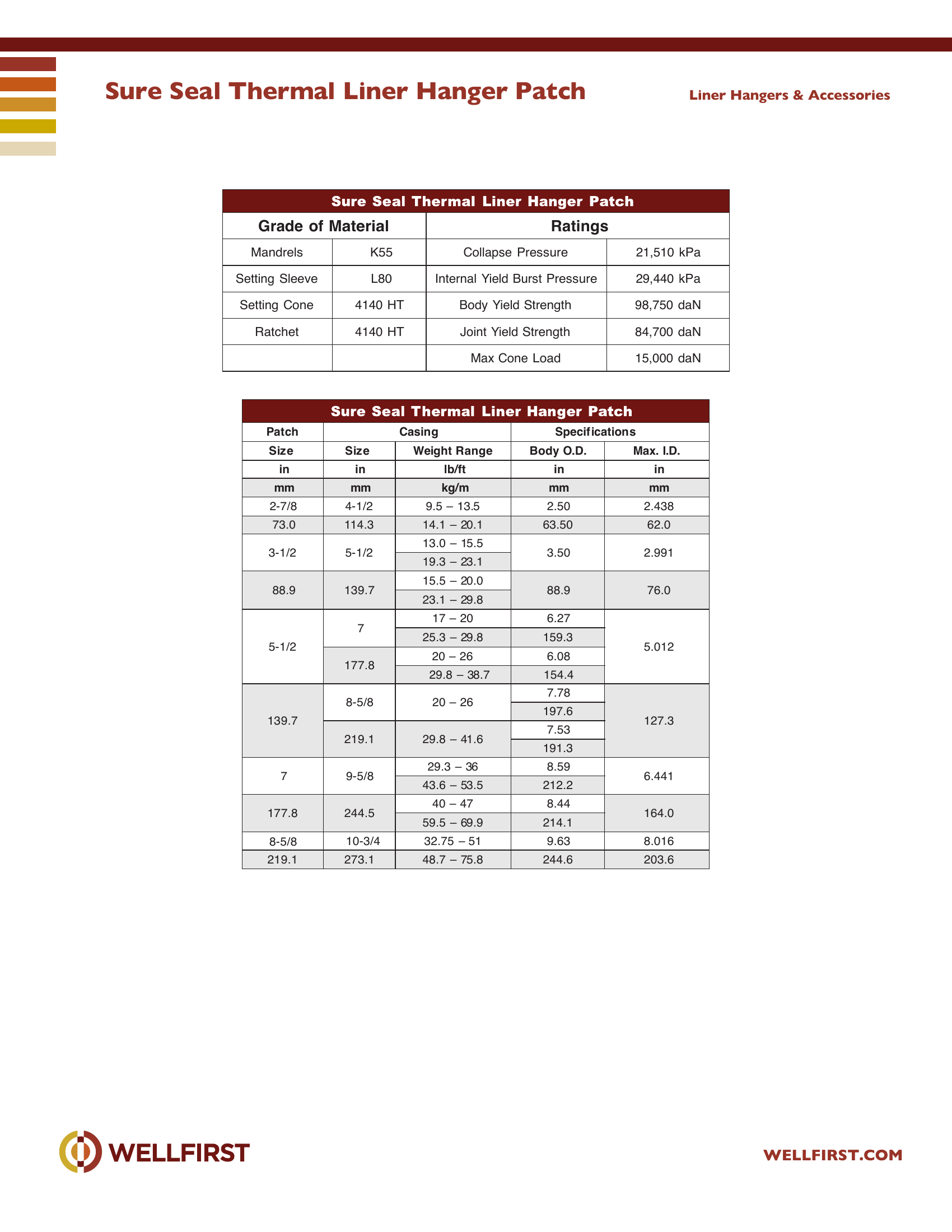
Patch Size inCasing Size inWeight Range lb/ftSpecif ications Body O.D. inMax. I.D. in
2-7/84-1/29.5 – 13.52.502.438
73.0114.314.1 – 20.163.5062.0
3-1/25-1/213.0 – 15.53.502.991
19.3 – 23.1
15.5 – 20.0
88.9139.788.976.0
23.1 – 29.8
5-1/2717 – 206.275.012
25.3 – 29.8159.3
20 – 266.08
177.8
29.8 – 38.7154.4
8-5/820 – 267.78
197.6
139.7127.3
7.53
219.129.8 – 41.6
191.3
79-5/829.3 – 368.596.441
43.6 – 53.5212.2
40 – 478.44
177.8244.5164.0
59.5 – 69.9214.1
8-5/810-3/432.75 – 519.638.016
219.1273.148.7 – 75.8244.6203.6
Grade of MaterialK55 L80Ratings Collapse Pressure21,510 kPa 29,440 kPa
Setting Cone4140 HTBody Yield Strength98,750 daN
Ratchet4140 HTJoint Yield Strength84,700 daN
Max Cone Load15,000 daN

Complete dimensional data, part numbering and setting procedures are in the PDF.
Casing Patches|•| 
Full data sheet (PDF)
Sure Seal Thermal Liner Hanger

Sure Seal Thermal Liner Hanger

PDF
Sure Seal Thermal Liner Hanger

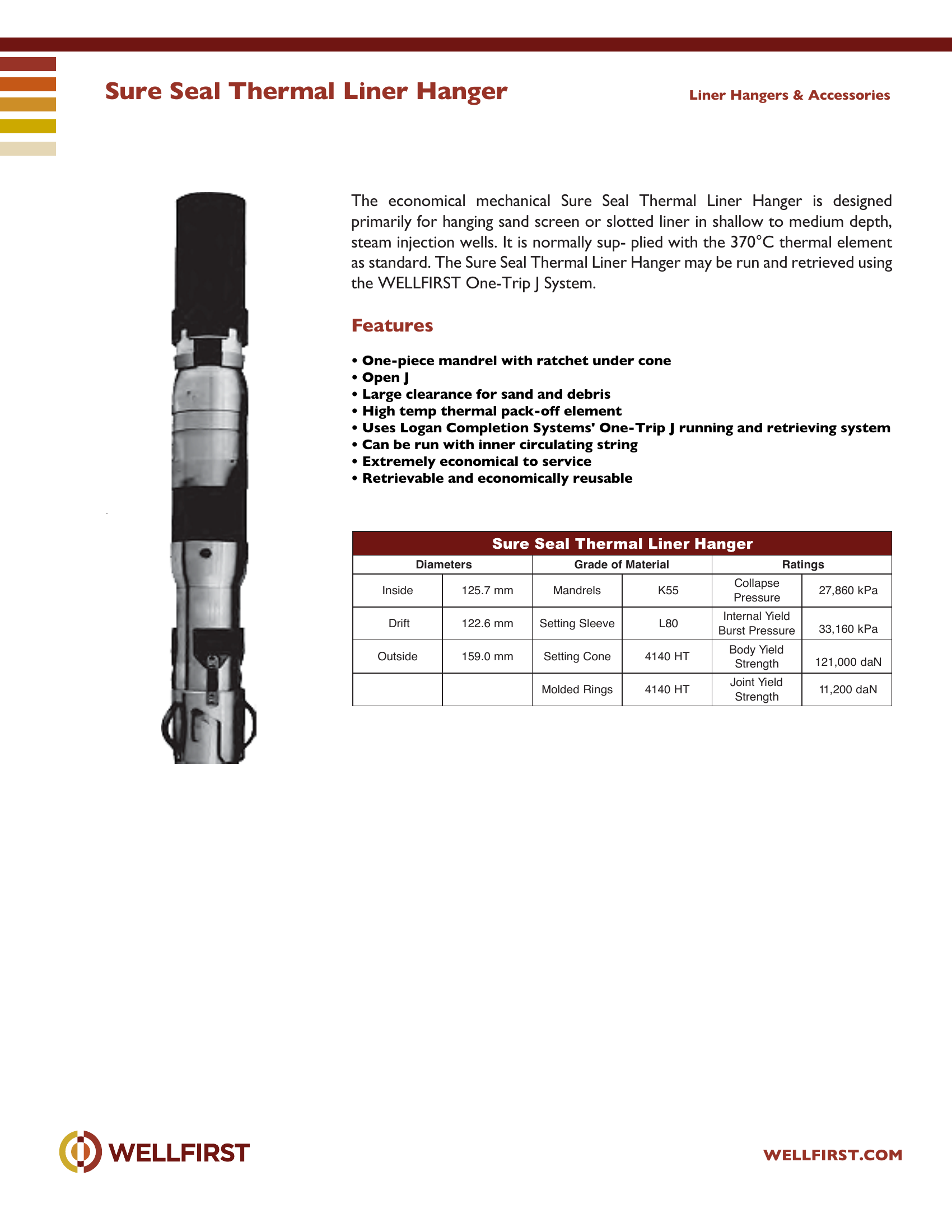
Sure Seal Thermal Liner Hanger The economical mechanical Sure Seal Thermal Liner Hanger is designed primarily for hanging sand screen or slotted liner in shallow to medium depth, steam injection wells. It is normally sup- plied with the 370°C thermal element as standard. The Sure Seal Thermal Liner Hanger may be run and retrieved using the WELLFIRST One-Trip J System.

Key features
  • One-piece mandrel with ratchet under cone
  • Open J
  • Large clearance for sand and debris
  • High temp thermal pack-off element
  • Uses Logan Completion Systems' One-Trip J running and retriev ing system
  • Can be run with inner circulating string
Data sheet tables
Diameters Inside Drift125.7 mm 122.6 mmGrade of MaterialK55 L80Ratings Collapse Pressure27,860 kPa 33,160 kPa
Outside159.0 mmSetting Cone4140 HTBody Yield Strength121,000 daN
Molded Rings4140 HTJoint Yield Strength11,200 daN

Complete dimensional data, part numbering and setting procedures are in the PDF.
Casing Patches|•| 
Full data sheet (PDF)
Wedge Wire Sand SCreen

Wedge Wire Sand SCreen

PDF
Wedge Wire Sand SCreen

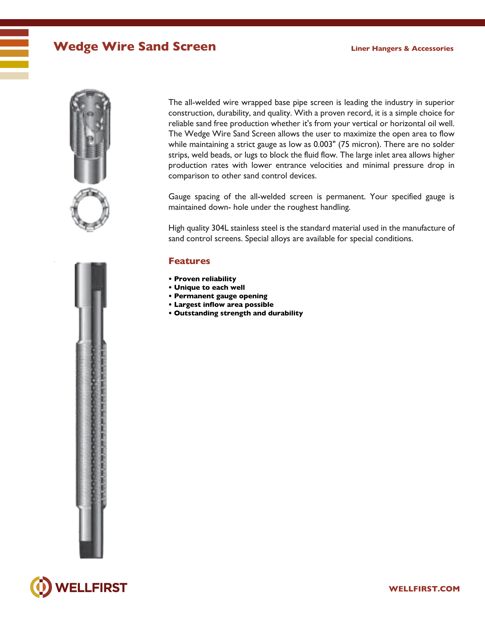
Wedge Wire Sand Screen The all-welded wire wrapped base pipe screen is leading the industry in superior construction, durability, and quality. With a proven record, it is a simple choice for reliable sand free production whether it's from your vertical or horizontal oil well. The Wedge Wire Sand Screen allows the user to maximize the open area to flow while maintaining a strict gauge as low as 0.003" (75 micron). There are no solder strips, weld beads, or lugs to block the fluid flow. The large inlet area allows higher production rates with lower entrance velocities and minimal pressure drop in comparison to other sand control devices. Gauge spacing of the all-welded screen is permanent. Your specified gauge is maintained down- hole under the roughest handling. High quality 304L stainless steel is the standard material used in the manufacture of sand control screens. Special alloys are available for special conditions.

Key features
  • Proven reliability
  • Unique to each well
  • Permanent gauge opening
  • Largest inflow area possible
  • Outstanding strength and durability Liner Hangers & Accessories

Complete dimensional data, part numbering and setting procedures are in the PDF.

Casing Patches|•| 
Full data sheet (PDF)