Type C Anti-Rotation Anchor
Type C Anti-Rotation Anchor
Type C Anti-Rotation Anchor The Type C Anti-Rotation Anchor is used to prevent tubing back off inprogressive cavity pump applications. Run as an integral part of the tubing string, the anchor automatically sets when tubing torque is present to prevent rotation of the tubing string.
Key features
- Compact design allows for a large gas by-pass area
- Rocker drag slip for reliable setting and releasing
- No set screws
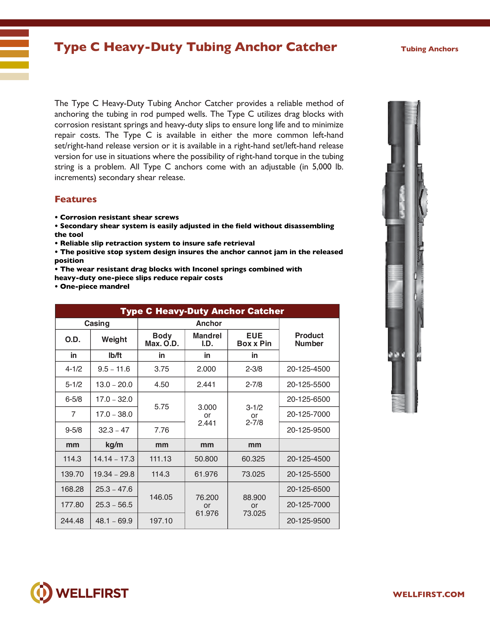
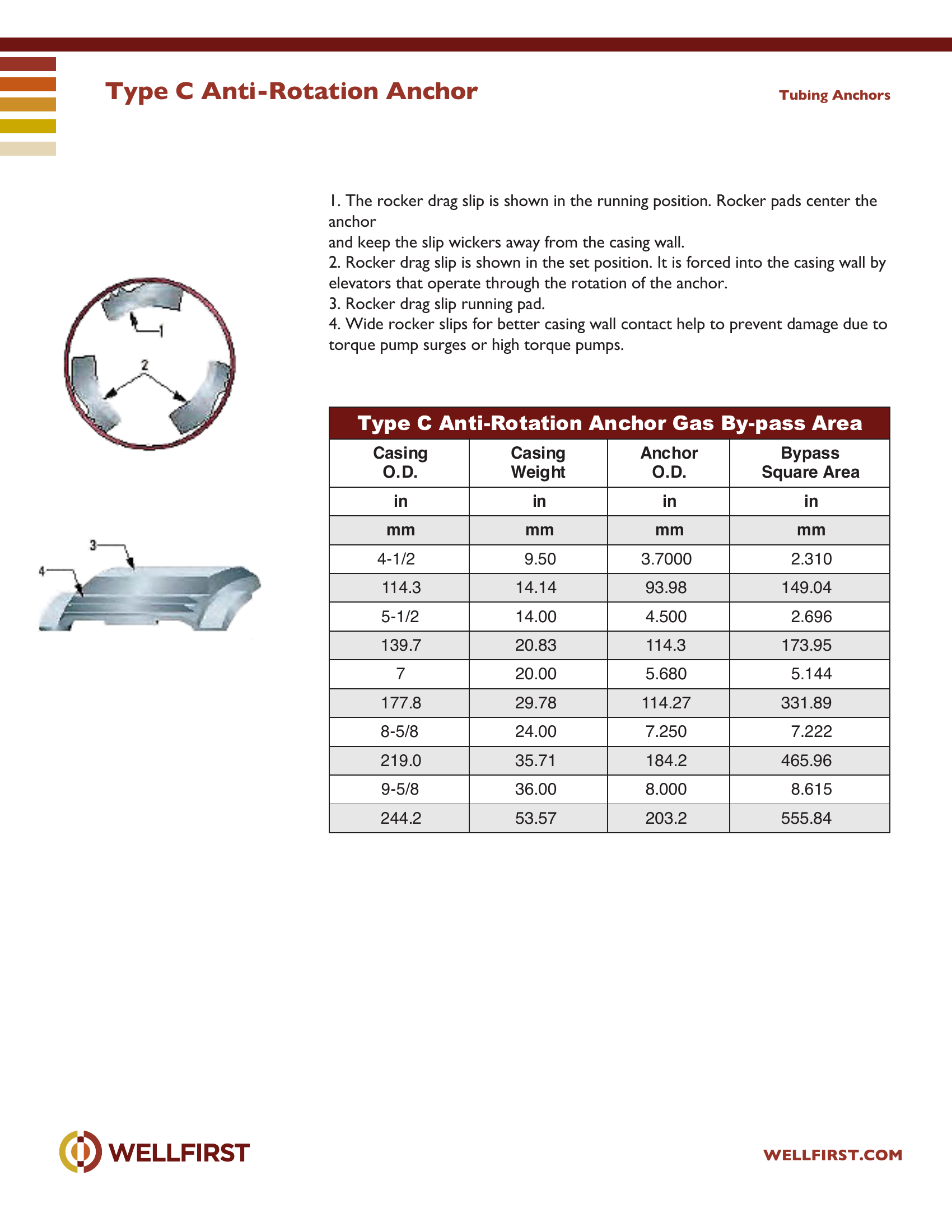
- One-piece mandrel Operation The Type C Anti-Rotation Anchor is simply run to depth with the pump. When torque is applied to the tubing, the wickers on the rocker drag slip engage the To release, rotate the tubing a small amount to the left to ensure the slips are Tubing Anchors Casing Ancho r Torqu e Tested Body I.D. Standard Box x Pin in lbs/ft in in in in in mm kg/m mm mm mm mm mm 5-1/2 13 – 20 4. 77 8 5. 04 4 4. 50 0 2.44 2-7/8 EUE 2,500 139.7 19.3 – 29.7 121.3 128.1 114.3 62.0 73.00 348 7 17 – 26 6.276 6.538 5.680 3.00 3-1/2 EUE 4,000 55 5 177.8 25.2 – 38.7 159.4 166.0 114.28 76.2 88.90 8-5/8 24 – 44 7.625 8.191 7.250 3.00 3-1/2 EUE 76.2 88.90 219.0 35.7 – 65.5 193.7 208.0 184.0 4.00 4-1/2 EUE 101.6 114.30 9-5/8 32 – 53.5 8.435 9.001 8.000 3.00 3-1/2 EUE 76.2 88.90 244.5 47.6 – 79.6 214.2 228.6 203.0 4.00 4-1/2 EUE 101.6 114.30 Type C Anti-Rotation Anchor WELLFIRST.COM Tubing Anchors Casing Casing Weight Anchor Bypass Square Area in in in in mm mm mm mm 4-1/2 9.50 3.7000 2.310 114.3 14.14 93.98 149.04 5-1/2 14.00 4.500 2.696 139.7 20.83 114.3 173.95 7 20.00 5.680 5.144 177.8 29.78 114.27 331.89 8-5/8 24.00 7.250 7.222 219.0 35.71 184.2 465.96 9-5/8 36.00 8.000 8.615 244.2 53.57 203.2 555.84 1. The rocker drag slip is shown in the running position. Rocker pads center the anchor 2. Rocker drag slip is shown in the set position. It is forced into the casing wall by Wide rocker slips for better casing wall contact help to prevent damage due to
Data sheet tables
| Casing Anchor Max. | Weight lbs/ft | Min. I.D. in | Max. I.D. in | Max. O.D. Body in | I.D. in | Standard Box x Pin in | |
|---|---|---|---|---|---|---|---|
| 5-1/2 | 13 – 20 | 4.778 | 5.044 | 4.500 | 2.44 | 2-7/8 EUE | 2,500 |
| 139.7 | 19.3 – 29.7 | 121.3 | 128.1 | 114.3 | 62.0 | 73.00 | 348 |
| 7 | 17 – 26 | 6.276 | 6.538 | 5.680 | 3.00 | 3-1/2 EUE | 4,000 555 |
| 177.8 | 25.2 – 38.7 | 159.4 | 166.0 | 114.28 | 76.2 | 88.90 | |
| 8-5/8 | 24 – 44 | 7.625 | 8.191 | 7.250 | 3.00 | 3-1/2 EUE | |
| 76.2 | 88.90 | ||||||
| 4.00 | 4-1/2 EUE | ||||||
| 219.0 | 35.7 – 65.5 | 193.7 | 208.0 | 184.0 | |||
| 101.6 | 114.30 | ||||||
| 9-5/8 | 32 – 53.5 | 8.435 | 9.001 | 8.000 | 3.00 | 3-1/2 EUE | |
| 76.2 | 88.90 | ||||||
| 4.00 | 4-1/2 EUE | ||||||
| 244.5 | 47.6 – 79.6 | 214.2 | 228.6 | 203.0 | |||
| 101.6 | 114.30 |
| Casing Casing Anchor | in mm | in mm | in mm |
|---|---|---|---|
| 4-1/2 | 9.50 | 3.7000 | 2.310 |
| 114.3 | 14.14 | 93.98 | 149.04 |
| 5-1/2 | 14.00 | 4.500 | 2.696 |
| 139.7 | 20.83 | 114.3 | 173.95 |
| 7 | 20.00 | 5.680 | 5.144 |
| 177.8 | 29.78 | 114.27 | 331.89 |
| 8-5/8 | 24.00 | 7.250 | 7.222 |
| 219.0 | 35.71 | 184.2 | 465.96 |
| 9-5/8 | 36.00 | 8.000 | 8.615 |
| 244.2 | 53.57 | 203.2 | 555.84 |
Complete dimensional data, part numbering and setting procedures are in the PDF.